Foaming equipment, foaming technology and foaming technology of refrigeration plant

A foaming equipment and process technology, applied in the field of refrigeration equipment manufacturing, can solve the problems of limited production capacity, high cost, high thermal conductivity, etc., and achieve the effects of saving foaming raw materials, ensuring foaming quality, and reducing time cycles

Active Publication Date: 2015-01-07
HEFEI MIDEA REFRIGERATOR CO LTD +1
View PDF4 Cites 6 Cited by
  • Summary
  • Abstract
  • Description
  • Claims
  • Application Information

AI Technical Summary

Problems solved by technology

[0006] 1. Part of the air that is not discharged in time during the foaming process will penetrate into the foaming material and form large pores, resulting in the formation of local thermal insulation weak points in the box, and the overall thermal conductivity is high;
[0007] 2. The rapid expansion of the foaming material inside the box and the high pressure inside the box caused by poor exhaust prolong the time period for the foaming material to fill the entire box, limiting the production capacity;
[0008] 3. Due to the longer filling cycle and the increase in hardness of the foaming material during the foaming process, while the fluidity and plasticity decrease and other factors, the density of the foaming material near the filling port is higher, and it is far away from the filling port. The density of the foam material is low, which makes the thermal conductivity of the whole box uneven and the individual differences of batch products are large
[0009] 4. In the actual production of refrigeration equipment, due to the above shortcomings, it is often necessary to fill more foaming materials to achieve the corresponding thermal insulation performance, resulting in higher costs, as well as many problems such as environmental protection and energy involved.

Method used


Image

  • Foaming equipment, foaming technology and foaming technology of refrigeration plant
  • Foaming equipment, foaming technology and foaming technology of refrigeration plant
  • Foaming equipment, foaming technology and foaming technology of refrigeration plant

Examples


Embodiment 1

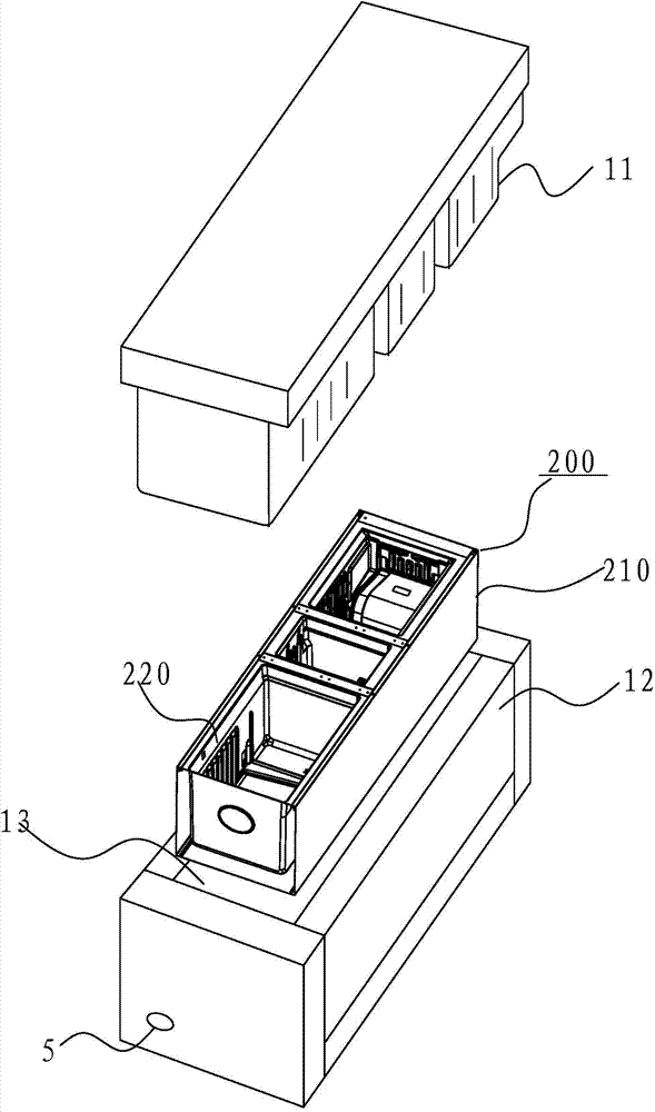
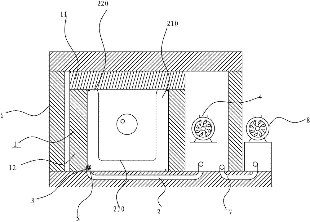
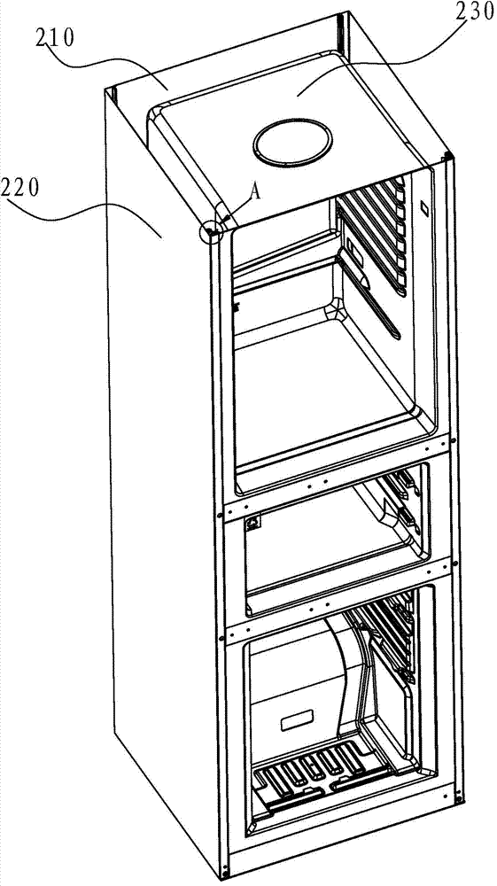
[0082] In this embodiment, the airway is designated 30a. like Figure 5-Figure 8 As shown, the airway 30a is provided with a partition 301a, and the partition 301a extends along the axial direction of the airway 30a to divide the inner cavity of the airway 30a into at least two spaces, and can play a role in supporting the strength of the airway 30a. effect. A plurality of air holes 302 a are formed on the wall of the air conduit 30 a to enhance the air extraction effect for each area in the foaming space 210 . Optionally, the air holes 302a are distributed linearly or spirally along the axial direction of the airway 30a.

[0083] like Figure 5 and Image 6 As shown, in one example of the present invention, the cross-section of the baffle 301a is rectangular, that is, the baffle 301a can be a flat plate so that the cross-section of the air duct 30a is approximately "day" shaped, that is, the baffle 301a will The lumen of the airway tube 30a is divided into two spaces. l...

Embodiment 2

[0094] In this embodiment, the airway is designated 30b. like Figure 9-Figure 16 As shown, an air groove 301b extending along the axial direction is formed on the wall of the air duct 30b, so that the cross section of the air duct 30b is in a "C" shape, so as to enhance the suction effect of each area in the foaming space 210. Optionally, in an example of the present invention, the air groove 301b has a flange extending radially outward along the air conduit 30b, such as Figure 9 and Figure 10 shown.

[0095] like Figure 9 As shown, in an example of the present invention, from the first end of the air conduit 30b (ie the end close to the suction port 211 ) to the second end opposite the first end (ie the end away from the suction port 211 ), the air groove The width of 301b is uniform along the axial direction of air conduit 30b. Optionally, the width of the air groove 301b is 1-3 mm. Further optionally, the width of the air groove 301b is 1.5mm.

[0096] In another...

Embodiment 3

[0102] In this embodiment, the airway is designated 30c. like Figure 17-Figure 18 As shown, the airway tube 30c includes an open tube 301c and a clip 302c, wherein the tube wall of the open tube 301c is provided with an opening 3010 extending along its axial direction, and the clip 302c is slidably provided on the open tube 301c to open and close the The opening 3010 is closed. Optionally, the clip 302c is connected with the open tube 301c in a manner of fitting with a chute.

[0103] Similar to the inner sleeve in the second embodiment, when the foaming space 210 needs to be pumped, the clip 302c is drawn out, and thus the gas in each area in the foaming space 210 is drawn out through the opening pipe 301c, thereby negative Pressure can be uniformly transmitted everywhere. When the gas in the foaming space 210 is exhausted, the clip 302c is inserted into and engaged with the opening 3010 of the opening tube 301c, thereby closing the air guide tube 30c, thereby preventing ...


PUM


Abstract

The invention discloses foaming equipment, a foaming technology and a foaming technology of a refrigeration plant. The foaming equipment is used for foaming a pre-assembling component; a foaming space is limited in the pre-assembling component; the foaming equipment comprises a foaming mould, a first air exhaust mechanism, a second air exhaust mechanism and a first negative pressure providing device. The foaming mould comprises a first mould body and a second mould body; the first mould body and the second mould body are matched to limit a mould cavity; the first air exhaust mechanism is communicated with the mould cavity; the second air exhaust mechanism comprises an air guide pipe fixedly arranged in the foaming space; the air guide pipe comprises an opening pipe and a clamping strip, an opening extending in the axial direction of the opening pipe is formed in the pipe wall of the opening pipe, and the clamping strip can be arranged on the opening pipe in a sliding mode to seal the opening. The first negative pressure providing device is connected with the first air exhaust mechanism and used for forming negative pressure in the foaming space. According to the foaming equipment, air negative pressure can be evenly transmitted to the foaming space, and therefore the heat preservation performance of a heat preservation layer obtained after foaming is better, foaming raw materials can be saved, and the cost is reduced.

Description

[0001] This application is a divisional application of Chinese Patent Application No. 201110007835.6, the name of the invention is "foaming equipment, foaming process and foaming process of refrigeration equipment", and the applicant is "Midea Hefei Refrigerator Co., Ltd., Hefei Hualing Co., Ltd.". technical field [0002] The invention relates to the field of refrigeration equipment manufacturing, in particular to a foaming equipment, a foaming process using the foaming equipment and a foaming process of the refrigeration equipment. Background technique [0003] At present, the refrigeration equipment on the market is mainly composed of a refrigeration system and a thermal insulation box. The thermal insulation box is generally made by the following processes: [0004] Assemble the outer shell and inner liner of the refrigeration equipment into a relatively closed shell, and set a filling port for foaming raw materials on one end face of the shell, and store the box in a hig...

Claims


Application Information

Patent Timeline
Patent Type & Authority Applications(China)
IPC IPC(8): B29C44/02B29C44/58B29C44/34
Inventor 石祥祚许进
Owner HEFEI MIDEA REFRIGERATOR CO LTD
Why Eureka
Try Eureka