Comprehensive utilization device for inferior coal, biomass and solid waste and working method
A solid waste and working method technology, which is applied in the field of comprehensive waste utilization devices, can solve the problems of single waste conversion products and low equipment conversion efficiency, and achieve the effects of high process efficiency, high utilization rate, and high fuel utilization rate
- Summary
- Abstract
- Description
- Claims
- Application Information
AI Technical Summary
Problems solved by technology
Method used
Image

Examples
Embodiment 1
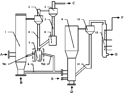
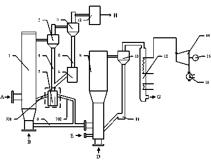
[0029] Such as figure 2 As shown, a device for comprehensive utilization of low-quality coal, biomass and solid waste, including a circulating fluidized bed gasifier 1, a first cyclone separator 2, a second cyclone separator 3, a first feeding pipe 4, Second feeding pipe 5, U-shaped feeding device 6, M-shaped feeding device 7, slag discharge pipe 8, circulating fluidized bed boiler 9, third cyclone separator 10, second feeding pipe 11, flue 12 , Gas purification device 13, steam turbine 14, generator 15 and condenser 16. The upper part of the circulating fluidized bed gasifier 1 is connected to the upper part of the first cyclone separator 2, the lower part of the circulating fluidized bed gasifier 1 is connected to the lower part of the circulating fluidized bed boiler 9 through the slagging pipe 8, and the lower part of the first cyclone separator 2 Connect to the top of the M type feeder 7 through the first feeding pipe 4, the top of the first cyclone separator 2 is conne...
Embodiment 2
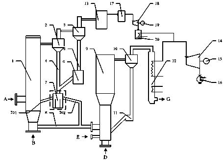
[0032] Such as image 3 As shown, a device for comprehensive utilization of low-quality coal, biomass and solid waste, the device has the same structure as that of Embodiment 1, but it also adds a combustion chamber 17, a gas turbine 18, a second generator 19, and a waste heat boiler 20. Among them, the combustion chamber 17 is connected to the outlet of the gas purification device 13, and the gas turbine 18 is connected to the combustion chamber 17, the second generator 19 and the waste heat boiler 20 respectively, and the waste heat boiler 20 is connected to the circulating fluidized bed boiler 9 through a steam pipe. The steam pipeline is connected, and the other end of the steam pipeline is connected to the steam turbine 14.
[0033] The device in Example 2 can realize gas-steam combined cycle power generation. Low-quality coal, biomass, and solid waste are reacted in the circulating fluidized bed gasifier 1, and the products pass through the first cyclone separator 2 an...
PUM
 Abstract
Description
Claims
Application Information
 - R&D
- Intellectual Property
- Life Sciences
- Materials
- Tech Scout
- Unparalleled Data Quality
- Higher Quality Content
- 60% Fewer Hallucinations
Browse by: Latest US Patents, China's latest patents, Technical Efficacy Thesaurus, Application Domain, Technology Topic, Popular Technical Reports.
© 2025 PatSnap. All rights reserved.Legal|Privacy policy|Modern Slavery Act Transparency Statement|Sitemap|About US| Contact US: help@patsnap.com