
Bathroom floor drain embedded sewer line impermeability device

A technology for toilets and water pipes is applied in the field of water supply and drainage of housing construction, which can solve the problems of large difference in linear expansion coefficient and linear expansion coefficient, damage to the adhesion between PVC pipes and concrete, and easy rust and corrosion of metal pipes.

Inactive Publication Date: 2015-01-07
HOHAI UNIV
View PDF8 Cites 5 Cited by
  • Summary
  • Abstract
  • Description
  • Claims
  • Application Information

AI Technical Summary

Problems solved by technology

[0002] At present, the sewer pipe material under the floor drain of the building toilet is basically PVC pipe and metal pipe. Because the metal pipe is easy to rust and corrode, the material of the sewer pipe under the floor drain of the building toilet is mostly PVC pipe at present, but the linear expansion coefficient of PVC pipe The linear expansion coefficient of concrete is quite different, especially after taking a hot bath, when the temperature difference changes greatly, the temperature stress is more likely to damage the bonding force between the PVC pipe and concrete, and the ground often accumulates in the hot bath. Water, use the toilet absorber to absorb the accumulated water in the floor drain and drain the water. At this time, the PVC pipe in the concrete is pulled by the toilet absorber. In the water pipe section, shortly after use, water seepage often flows to the downstairs toilet along the cemented crack between the PVC pipe and the concrete, so there are deficiencies in the existing technology

Method used


Image

  • Bathroom floor drain embedded sewer line impermeability device
  • Bathroom floor drain embedded sewer line impermeability device

Examples


Embodiment Construction

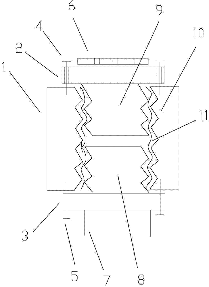
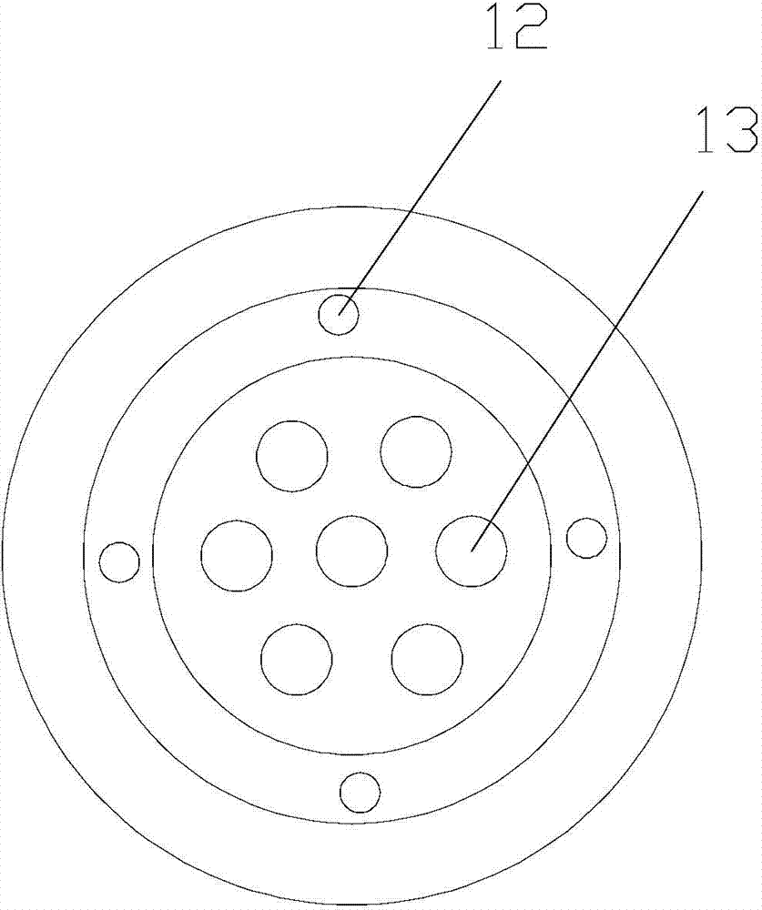
[0011] Control attached figure 1 , the floor drain 6 is connected to the upper screw cap 2, the upper screw cap 2 is connected to the upper end of the upper half of the outer tooth plastic pipe 9, the upper screw cap 2 is provided with a cap screw hole 12 and a drain hole 13, and the upper screw cap 2 passes through the upper screw 4 is connected with the pre-embedded metal casing 1, the lower screw cap 3 is connected to the lower end of the lower half of the outer teeth plastic tube 8, the lower screw cap 3 is provided with screw holes 12, and the lower screw cap 3 is connected to the embedded The metal casing 1 is connected, the lower screw cap 3 is connected with the upper end of the sewer pipe 7, and the sewer pipe 7 is made of PVC material. An elastic-plastic waterproof tape 11 is set between the corrugated teeth of the buried metal casing 1, and a small gap is set between the bottom edge of the upper half of the outer tooth plastic tube 9 and the upper edge of the lower ...


PUM


Abstract

The invention discloses a bathroom floor drain embedded sewer line impermeability structure device which comprises an embedded metal sleeve, a floor drain, an upper half outer tooth plastic pipe, a lower half outer tooth plastic pipe, an elastic plastic water-retaining adhesive tape and a sewer pipe, wherein an upper screw cap is arranged at the upper end of the embedded metal sleeve; a lower screw cap is arranged at the lower end of the embedded metal sleeve; the upper end of the upper half outer tooth plastic pipe is connected with the upper screw cap; the floor drain is arranged on the upper screw cap; the lower end of the lower half outer tooth plastic pipe is connected with the lower screw cap; the sewer pipe is connected to the lower end of the lower screw cap; and a distance is reserved between the bottom edge of the upper half outer tooth plastic pipe and the upper edge of the lower half outer tooth plastic pipe. Compared with the prior art, the bathroom floor drain embedded sewer line impermeability structure device disclosed by the invention adopts the design of similar deformation, elastic plastic gap filling and stress transfer decomposition, is simple in structure, good in impermeability effect, economic, durable, convenient to maintain and large in popularization space and is suitable for building bathroom floor drain sewer pipeline embedded sections.

Description

technical field [0001] The invention is an anti-seepage device for the pre-buried sewer pipe of the washroom floor drain designed for the sewer pipe in the pre-buried section under the floor drain of the restroom of a building that often seeps into the downstairs washroom, and belongs to the field of building water supply and drainage. Background technique [0002] At present, the sewer pipe material under the floor drain of the building toilet is basically PVC pipe and metal pipe. Because the metal pipe is easy to rust and corrode, the material of the sewer pipe under the floor drain of the building toilet is mostly PVC pipe at present, but the linear expansion coefficient of PVC pipe The linear expansion coefficient of concrete is quite different, especially after taking a hot bath, when the temperature difference changes greatly, the temperature stress is more likely to damage the bonding force between the PVC pipe and concrete, and the ground often accumulates in the hot ...

Claims


Application Information

Patent Timeline
IPC IPC(8): E03C1/12F16L5/02
CPCE03F5/0409
Inventor 刘孝洋刘亮蒋新会
Owner HOHAI UNIV
Learn More