Tower type oil sucking machine

A tower pumping unit and sucker rod technology, which is applied in the production of fluids, wellbore/well components, earth-moving drilling, etc., can solve the problem of high power consumption, low operating efficiency of beam pumping units, and reliable transmission chain. The performance and service life restrict the development of beamless pumping units, so as to improve the service life and avoid impact.

Inactive Publication Date: 2015-01-07
BEIHANG UNIV +1
0 Cites 2 Cited by

AI-Extracted Technical Summary

Problems solved by technology

However, the beam pumping unit has low operating efficiency and consumes a lot of electricity. According to statistics, its efficiency is only about 15%-20%.
With the application of various new transmission devices, various beamless pumping units have also appeared on the produ...

Method used

[0037] Further, it needs to be understood that at the junction of the upper stroke and the lower stroke, the spring set will release the elastic potential energy, gradually accelerate the counterweight 4, and avoid the impact of sudden movement. For example, when the upper stroke compresses the second spring, and the moving speed of the counterweight 4 is zero at this t...

Abstract

The invention relates to a tower type oil sucking machine, which comprises a machine frame, fixed pulleys, a connecting chain, a balancing weight, a sucker rod and a motor, wherein the fixed pulleys are arranged at the top end of the machine frame; the connecting chain is transmission cooperation with the fixed pulleys; the two ends of the connecting chain are respectively connected with the balancing weight and the sucker rod; the motor drives the balancing weight and the sucker rod to vertically move in opposite directions; the tower type oil sucking machine also comprises spring groups; the spring groups are fixedly arranged on the machine frame and are right against the balancing weight; and the spring groups can be compressed by the balancing weight in the vertical moving process of the balancing weight. In the upstroke and the downstroke of the oil sucking machine, the speed cannot suddenly change due to the effect of the spring groups; the acceleration cannot suddenly change; the occurrence of impact is avoided; and the service life of an oil sucking machine system is prolonged.

Application Domain

Technology Topic

Image

  • Tower type oil sucking machine
  • Tower type oil sucking machine
  • Tower type oil sucking machine

Examples

  • Experimental program(2)

Example Embodiment

[0019] Example one:
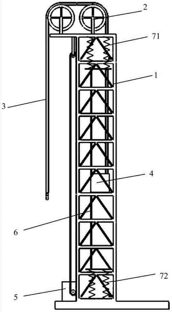
[0020] Such as figure 1 As shown, the motor 5 is fixedly arranged on the frame 1, and the motor 5 drives the fixed pulley 2 to rotate, driving the counterweight 4 and the sucker rod to move up and down in the opposite direction.

Example Embodiment

[0021] Embodiment two:
[0022] Such as figure 2 As shown, the tower pumping unit further includes a chain 6, which is connected end to end to form a closed loop, the counterweight 4 is fixedly connected to the chain 6; the motor 5 is fixedly arranged on the frame 1, and the motor 5 drives The chain 6 drives the counterweight 4 and the sucker rod to move up and down in the opposite direction. That is, the chain 6 driven by the motor 5, the two ends of the chain 6 are connected end to end to form a closed loop, and the counterweight 4 is fixedly connected to the chain 6. It can be understood that the counterweight 4 is connected between the chain 3 and the chain 6 mentioned above. Driven, it can move up and down.
[0023] Optionally, the tower pumping unit also has a chain positioning device, which is used for positioning the chain and restricting the movement path of the chain. Optionally, there are at least two chain positioning devices: a first chain positioning device and a second chain positioning device, wherein the first chain positioning device is arranged at the top of the frame, and the second chain positioning device is arranged at the bottom of the frame, and The first chain positioning device and the second chain positioning device are arranged opposite to each other.
[0024] Optionally, as in the above-mentioned movement form of the counterweight 4 and sucker rod, in order to ensure that the counterweight 4 can move smoothly between the first spring group 71 and the second spring group 72, the connection of the counterweight 4 The chain, at least in the part between the first spring group 71 and the second spring group 72, needs to move vertically so that the counterweight 4 can surging in the vertical direction. Therefore, in a preferred manner, The first chain positioning device may be located at the center of the first spring group 71, and the second chain positioning device may be located at the center of the second spring group 72. The above-mentioned "center position" respectively refers to the range where the first spring is projected on the top of the frame and the second spring group 72 is projected on the bottom of the frame.
[0025] The above-mentioned first chain positioning device and the second chain positioning device may be sprockets respectively. Taking the first and second sprocket as an example, the first sprocket is set on the top of the frame, and the second sprocket is set on the machine. The bottom end of the shelf. Of course, in the above-mentioned setting form of "center position", the most preferred is the center position of the projection, and when the pulley is used, one side of the pulley can be located at the center position. It should be understood that the sprocket is an optional embodiment, and other forms of structure can also be used in the present invention. For example, a fixed wheel can be directly used. It should also be understood that if the chain is replaced by a rope or other in the pumping unit The connection structure, the chain fixing device can also be changed accordingly.
[0026] In addition, it needs to be understood that the above-mentioned chain can also be replaced by other forms of structure, such as a steel wire rope.
[0027] The above two embodiments illustrate how the motor 5 drives the movement of the counterweight 4 and the sucker rod. The following is a unified description in combination with the above two embodiments.
[0028] In an optional embodiment, it further includes a reduction gearbox through which the motor 5 drives the chain to rotate (corresponding to the second embodiment) or drives the fixed pulley to rotate (corresponding to the first embodiment). Of course, the motor 5 may also be a numerically controlled motor 5, which directly changes the rotation speed, steering, etc. according to the settings.
[0029] In an alternative embodiment, the spring group includes at least one spring, that is, the first spring group 71 includes at least one spring; the second spring group 72 also includes at least one spring.
[0030] In an alternative embodiment, one end of each spring is connected to a contact plate, and the contact surface of the contact plate faces the counterweight 4, and the contact surface is perpendicular to the movement path of the counterweight 4. To be more specific: the first spring group 71 includes at least one spring, and a first contact plate connected to the spring, the first contact plate is located under the first spring group 71; the second spring group 72 includes at least one spring, and The second contact plate connected with the spring, the second contact plate is located above the second spring group 72, and the above-mentioned first contact plate and the second contact plate are opposite to each other. As mentioned above, it can be known that both the springs in the first spring group 71 and the springs in the second spring group 72 are firstly fixedly connected to the top or bottom end of the frame. This end can be called a fixed end, and the other One end is the movable end, which is the movable end connecting the first contact plate and the second contact plate. Because the counterweight 4 will perform work on the spring group (here for the convenience of description, the first spring group 71 and the second spring group 72 are collectively referred to as the spring group) during the movement process, in order to make the contact with the spring group more stable, Therefore, a contact plate is provided. The contact plate is a flat plate.
[0031] In an alternative embodiment, each of the springs in the spring set is 100-150cm long, the compression amount A is 15-40cm, and the elastic coefficient K=(G1+G2-W)/A; namely, the first spring set Each of the springs in 71 and the second spring group 72 has a length of 100-150cm, a compression amount A of 15-40cm, and a spring rate
[0032] K=(G 1 +G 2 -W)/A;……(1)
[0033] G1 is the weight of the sucker rod; G2 is the weight of the oil that the sucker rod can load; W is the weight of the counterweight 4.
[0034] It should be understood that the spring set includes at least one spring, and when the number of springs is more than one, each spring is arranged in parallel, and each spring faces the counterweight 4. Of course, through the above description, it should also be understood that facing the counterweight 4 means that the spring group can be counterweighted during the movement of the counterweight 4, or in a certain path along which the counterweight 4 moves. 4 Compression.
[0035] In order to facilitate the understanding of the function of the spring group, the third form is combined with the dynamic situation of the tower pumping unit as an example. Combining this example, the structure and principle of the tower pumping unit are further explained. When the sucker rod is on the upstroke (that is, the sucker rod rises upward): the motor 5 drives the chain, which in turn drives the counterweight 4 to move down, and because the counterweight 4 and the sucker rod are connected by the connecting chain 3, Therefore, the counterweight 4 moves downward to drive the sucker rod upward; the counterweight 4 continues to move downwards until it contacts the second spring group 72 and continues to compress the second spring group 72 downwards. , The counterweight 4 does work on the second spring group 72, and the second spring group 72 also stores the elastic potential energy. At the same time, the counterweight 4 gradually decelerates, and the acceleration gradually decreases, and will not drop to zero suddenly, avoiding the occurrence of impact .
[0036] When the sucker rod is in the downstroke (the sucker rod descends downward), the motor 5 drives the chain, which in turn drives the counterweight 4 to move upward. It can be known that the motor 5 can rotate forward or backward. The weight 4 and the sucker rod are connected by the connecting chain 3. Therefore, the counterweight 4 moves upward, which drives the sucker rod down; the counterweight 4 continues to move upward until it touches the first spring group 71, And continue to compress the first spring group 71 upward. At this time, the counterweight 4 does work on the first spring group 71, and the first spring group 71 also stores elastic potential energy. At the same time, the counterweight 4 gradually decelerates and the acceleration gradually decreases. Will not drop to zero suddenly, avoiding the occurrence of shocks.
[0037] Furthermore, it needs to be understood that at the boundary of the upstroke and the downstroke, the spring group will release the elastic potential energy, gradually accelerate the counterweight 4, and avoid the impact of sudden movement. For example, from the upstroke until the second spring is compressed, and the moving speed of the counterweight 4 is zero at this time, the second spring gradually releases the elastic potential energy and pushes the counterweight 4 to accelerate upward to start the downstroke. It can be seen that the upper and lower strokes In between, through the arrangement of the first spring group and the second spring group 72, sudden changes in acceleration are avoided, and impact is also reduced.
[0038] The above is for the third setting form of the spring group. The first form can only correspond to the downstroke, and the second form can only correspond to the upstroke.
[0039] In order to explain the present invention more clearly, the attached figure 2 , Shows the speed curves of the sucker rod of the existing pumping unit and the tower pumping unit of the present invention, and image 3 In the acceleration curve diagram, the dashed line represents the prior art pumping unit, which represents the tower pumping unit of the present invention. In the figure, the 0-t3 section is the upstroke, and the t3-t6 section is the downstroke. The states of each section are explained separately. Because the counterweight 4 is in contact with the first and second spring groups, the counterweight 4 is the main object of illustration , The sucker rod is just opposite to the moving direction of the counterweight 4:
[0040] 0-t1: The first spring releases the elastic potential energy, and the counterweight 4 moves downward and is gradually accelerated by the first spring;
[0041] t1-t2: The elastic potential energy of the first spring is released, and the counterweight 4 is separated from the first spring and moves downward at a uniform speed;
[0042] t2-t3: The counterweight 4 is in contact with the second spring and gradually decelerates to zero;
[0043] t3-t4: The second spring releases the elastic potential energy, and the counterweight 4 moves upward and is gradually accelerated by the second spring;
[0044] t4-t5: The elastic potential energy of the second spring is released, the counterweight 4 is separated from the second spring and moves upward at a uniform speed;
[0045] t5-t6: The counterweight 4 contacts the first spring and gradually decelerates to zero.
[0046] It needs to be understood that 0-t6 in the figure is only a truncated period. In practical applications, multiple periods of this period appear end to end.
[0047] It can be seen from the figure that the acceleration of the tower pumping unit of the present invention changes gradually regardless of whether it increases or decreases, which is different from the sudden change in acceleration of the pumping unit in the prior art. Therefore, the pumping unit of the present invention can Avoid shocks to increase service life.
[0048] The following describes the weight selection method of the counterweight 4, that is, the trim method of the tower pumping unit:
[0049] A simple description of the load characteristics of the tower pumping unit: the load on the upper and lower strokes of the pumping unit is very uneven. During the upper stroke, the pumping unit needs to lift the lifted weight (sucker rod) and the oil that can be loaded by the sucker rod During the downstroke, the lifted weight (sucker rod) can fall under its own weight, which makes the work of the power unit extremely uneven. It needs to be understood that in the actual operation process, the weight of the loadable oil is simulated by a hydraulic cylinder. The hydraulic cylinder is used to simulate the weight of the oil. Of course, the sucker rod and sucker rod can be simulated at the same time through the hydraulic cylinder. The weight of the loaded oil.
[0050] In order to make the work of the up and down stroke power devices even, the present invention adopts a configured balance mode, the weight of the counterweight can be obtained by the following formula, which is the least work:
[0051] Work on the stroke:
[0052] Y s = ∫ 0 t 3 F d dt = ∫ 0 t 3 ( G 1 + G 2 - w + f 1 + f 2 ) v n dt
[0053] = ( G 1 + G 2 - w + f 1 + f 2 ) ( A 1 + v 1 max t 2 + A 2 ) . . . . . . ( 2 )
[0054] Work on down stroke:
[0055] Y x = ∫ t 3 t 6 F d vdt = ∫ t 3 t 6 ( w - G 1 + f 1 + f 2 ) v n dt
[0056] = ( w - G 1 + f 1 + f 2 ) ( A 2 + v 4 max t 5 + A 1 ) . . . . . . ( 3 )
[0057] Work done throughout the stroke: Y = Y S +Y X
[0058] Work balance up and down: Y S =Y X
[0059] Weight of counterweight:
[0060] w = ( G 1 + G 2 + f 1 + f 2 ) ( A 1 + v 1 max t 2 + A 2 ) + ( G 1 - f 1 - f 2 ) ( A 2 + v 4 max t 5 + A 1 ) ( 2 A 2 + v 1 max t 2 + v 4 max t 5 + 2 A 1 ) . . . . . . ( 4 )
[0061] Where: G 1 -Sucker rod weight; G 2 -Liquid column weight (as mentioned above, it can be a hydraulic cylinder simulation); w- balance iron weight; n- various stages of the pumping unit (n=1, 2...6, which corresponds to the time period t0-t6 in the previous speed acceleration diagram) Similar); F 1 -The upward pulling force of the balance iron; F 2 -The upward pull of the sucker rod and liquid column load; v n -Pumping unit system speed (n=1, 2...6); A n -Total compression of the spring (n=1, 2...6); f 1 -Friction between motor and gearbox; f 2 -Friction between sucker rod and oil; Y S -Up-stroke motor 5 does work; Y X -Down-stroke motor 5 does work; Y-motor 5 does work in one stroke.

PUM

no PUM

Description & Claims & Application Information

We can also present the details of the Description, Claims and Application information to help users get a comprehensive understanding of the technical details of the patent, such as background art, summary of invention, brief description of drawings, description of embodiments, and other original content. On the other hand, users can also determine the specific scope of protection of the technology through the list of claims; as well as understand the changes in the life cycle of the technology with the presentation of the patent timeline. Login to view more.

Similar technology patents

Vehicle-mounted battery installation platform

InactiveCN104723304AAvoid shockRealize the adjustment of spatial postureWork benchesButt jointLinkage concept
Owner:王昕

Classification and recommendation of technical efficacy words

  • Avoid shock
  • Extend your life
Why Eureka
Try Eureka