An axial-radial three-degree-of-freedom hybrid magnetic bearing

A hybrid magnetic bearing, degree of freedom technology, applied in the direction of shaft and bearing, bearing, mechanical equipment, etc., can solve the problems of unfavorable rotor critical speed, long rotor axial length, large volume of magnetic bearing, etc., to achieve simple structure and improve bearing capacity. Ability, the effect of reducing the size

Inactive Publication Date: 2016-08-24
JIANGSU UNIV
View PDF7 Cites 0 Cited by
  • Summary
  • Abstract
  • Description
  • Claims
  • Application Information

AI Technical Summary

Problems solved by technology

[0004] At present, the axial-radial hybrid magnetic bearings researched at home and abroad are mainly divided into two structural forms: one is to separate the radial magnetic bearing from the axial magnetic bearing, and to separately control the axis and radial suspension. However, This structure has a long axial length of the rotor, which is not conducive to the increase of the critical speed of the rotor; the other is to integrate the axial and radial suspension control together, and the rotor is smaller, which is conducive to the increase of the critical speed of the rotor
[0005] Chinese Patent Publication No. CN101392795A, titled "An Outer Rotor Shaft-Radial Three Degrees of Freedom Hybrid Magnetic Bearing" and Chinese Patent Publication No. CN1737388A, titled "Three Degrees of Freedom AC / DC Radial-Axial Hybrid Magnetic Bearing and its The radial control current in "control method" is alternating current, which contains harmonic current, which is easy to cause eddy current loss
Chinese Patent Publication No. CN101149077A is named "Permanent Magnet Bias Axial Radial Magnetic Bearing", which requires 6 radial control coils and 2 annular permanent magnets. The volume of the magnetic bearing is large, and the power consumption of the magnetic bearing is high.

Method used


Image

  • An axial-radial three-degree-of-freedom hybrid magnetic bearing
  • An axial-radial three-degree-of-freedom hybrid magnetic bearing

Examples


Embodiment Construction

[0027] The present invention will be further described below in conjunction with accompanying drawing.

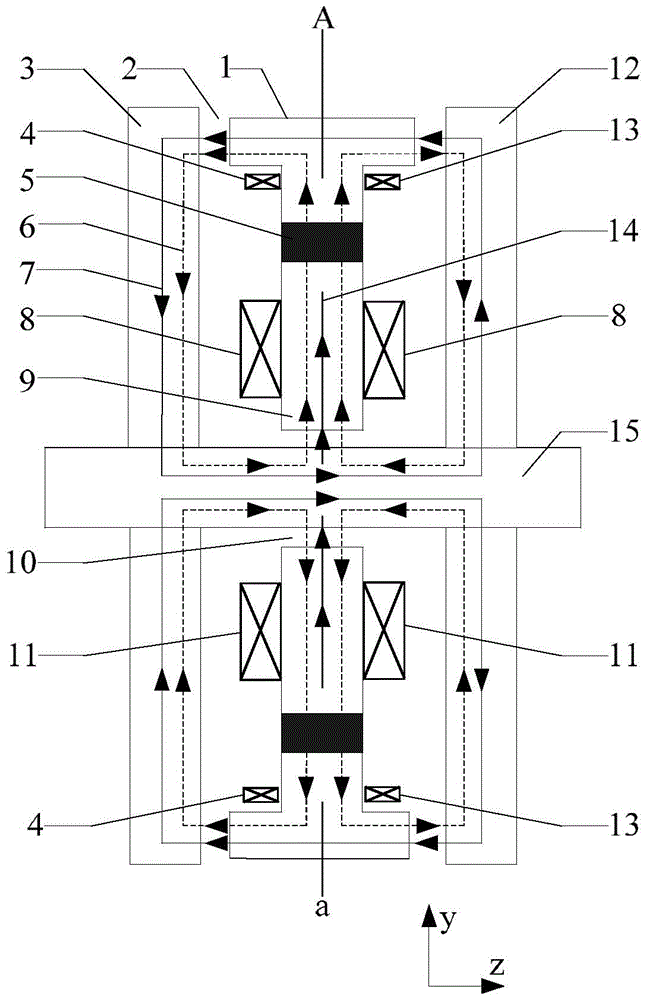
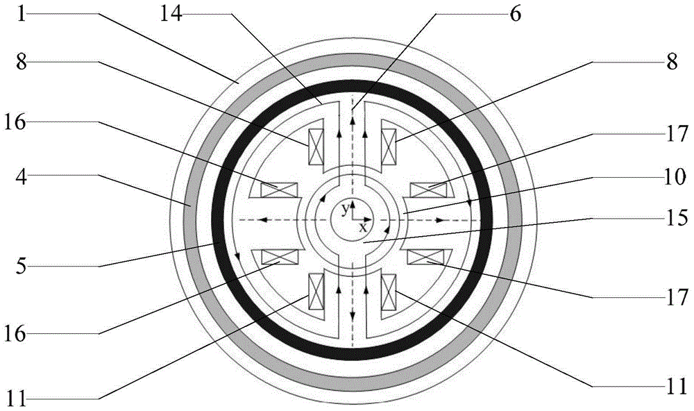
[0028] figure 1 A schematic diagram of the axial section and the magnetic flux circuit of the axial-radial three-degree-of-freedom hybrid magnetic bearing, figure 2 for figure 1 The A-a radial cross-section and schematic diagram of the magnetic flux circuit. The annular axial stator 1 has a "T"-shaped axial section and is made of electrical steel. The permanent magnetic ring 5 is made of rare earth material NdFeB, placed between the axial stator 1 and the radial stator 9, and mounted together to generate axial and radial bias fluxes simultaneously. The first axial control winding 4 and the second axial control winding 13 are respectively wound in the annular groove composed of the axial stator, the permanent magnet ring, the radial stator, the rotating shaft and two suction discs to generate Axial control flux. The upper radial control winding 8, the lower radial cont...


PUM


Abstract

The invention discloses an axial-radial three-degree-of-freedom hybrid magnetic bearing, which comprises an annular axial stator, a permanent magnet ring, a radial stator with four magnetic poles, an axial control winding, a radial control winding, a suction disk and a rotating shaft. The axial stator uses a radially magnetized permanent magnet ring to be placed between the axial stator and the radial stator, and they are mounted together. The axial control winding is wound in an annular groove composed of an axial stator, a permanent magnet ring, a radial stator, a rotating shaft and a suction disk. The radial control windings are respectively wound on the four magnetic poles of the radial stator. Two suction discs are respectively placed on both sides of the stator assembly. The invention greatly reduces the axial length of the magnetic bearing, and the levitation force can be made larger; the direct current is used for control, which effectively reduces or eliminates the eddy current loss; does not occupy too large radial and axial lengths, and increases the hybrid type The scope of application of the magnetic suspension bearing; the structure is simple, the control is convenient and easy to realize.

Description

technical field [0001] The invention relates to a non-mechanical contact magnetic bearing, in particular to an axial-radial three-degree-of-freedom hybrid magnetic bearing, which is suitable for axial non-contact suspension in high-speed flywheel energy storage, high-speed electric spindle, bearingless motor and other high-speed transmission fields support. Background technique [0002] Magnetic suspension bearing (magnetic bearing) is a kind of bearing that uses electromagnetic force to realize the stable levitation operation of the rotor system without mechanical contact. Compared with traditional mechanical bearings, magnetic bearings have the advantages of no friction, no wear, high speed, low noise and long life. Since there is no mechanical contact between the stator and the rotor, the rotor of the magnetic bearing can reach a very high speed, so it has broad application prospects in high-speed flywheel energy storage, high-speed electric spindle, bearingless motor an...

Claims


Application Information

Patent Timeline
Patent Type & Authority Patents(China)
IPC IPC(8): F16C32/04
Inventor 孙宇新董今越朱熀秋杜怿方志明
Owner JIANGSU UNIV
Why Eureka
Try Eureka