An inductive energy meter

An electric energy meter and inductive technology, applied in the field of inductive electric energy meters, can solve problems such as large fluctuations, and achieve the effects of reducing nonlinear errors, reducing errors, and small iron core silicon steel reluctance.

Active Publication Date: 2016-09-21
SHANGHAI JINLING INTELLIGENT ELECTRIC METER
View PDF10 Cites 0 Cited by
  • Summary
  • Abstract
  • Description
  • Claims
  • Application Information

AI Technical Summary

Problems solved by technology

However, due to the working principle of electromagnetic induction, the electromechanical induction type watt-hour meter has an overload characteristic limited to 4 to 6 times, and cannot achieve a flat load characteristic curve and a wide load range like an electronic watt-hour meter. Figure 9 and Figure 10 It is shown that after the overload current increases, the fluctuation is larger

Method used


Image

  • An inductive energy meter
  • An inductive energy meter
  • An inductive energy meter

Examples


Embodiment 1

[0033] Embodiment 1: Applied to single-phase induction electric energy meter

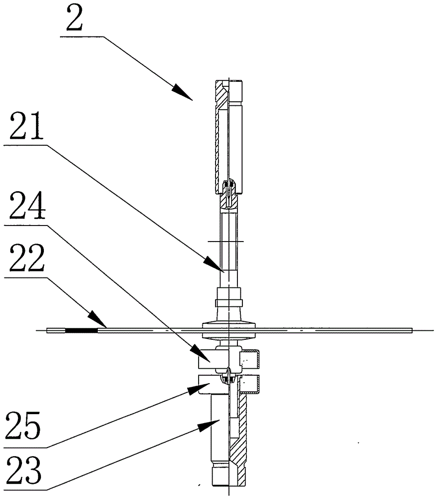
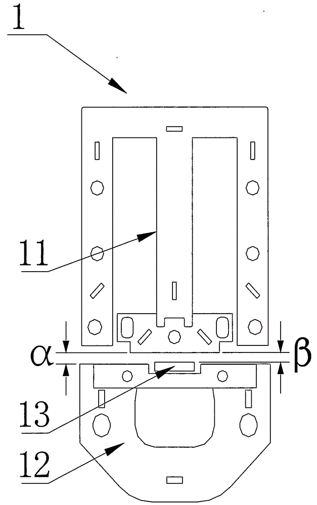
[0034] see figure 1 and figure 2 , a single-phase induction electric energy meter, including a driving element 1 and a rotating element 2, the rotating element 2 includes a rotating shaft 21, a rotating disk 22 and a lower shaft tip 23, the rotating disk 22 is movably connected with the rotating shaft 21; an upper magnetic ring 24 is arranged below the rotating disk 22 , the upper magnetic ring 24 is movably connected with the rotating shaft 21; the top of the lower shaft tip 23 is provided with a lower magnetic ring 25, and the lower magnetic ring 25 is fixedly connected with the lower shaft tip 23; the driving element 1 includes a voltage element 11, a current element 12 and a magnetic branch 13, the magnetic shunt 13 is arranged between the voltage element 11 and the current element 12, the distance α between the voltage element 11 and the current element 12 is 2.6 millimeters, and the distanc...

Embodiment 2

[0040] Embodiment 2: Applied to three-phase induction electric energy meter

[0041]Since the structure of the three-phase induction electric energy meter is similar to that of the single-phase induction electric energy meter, the structure of the three-phase induction electric energy meter is not shown in the drawings; the three-phase induction electric energy meter includes the driving element and the rotating element, and the rotating element It includes a rotating shaft, a turntable and a lower shaft tip, and the turntable and the rotating shaft are flexibly connected; an upper magnetic ring is arranged under the turntable, and the upper magnetic ring is flexibly connected with the rotating shaft; a lower magnetic ring is arranged on the top of the lower shaft tip, and the lower magnetic ring is connected to the lower shaft tip Fixed connection; the driving element includes a voltage element, a current element, and a magnetic shunt. The magnetic shunt is arranged between th...


PUM


Abstract

The invention belongs to the electric power measuring technology and particularly relates to an induction type electric energy meter of which a rated maximum current Imax is eight times as large as a basic current Ib. The induction type electric energy meter comprises driving elements and rotation elements, wherein the rotation elements comprise a rotation shaft, a rotation disc and a lower shaft tip, the rotation disc and the rotation shaft are in movable connection, a lower portion of the rotation disc is provided with an upper magnetic ring, the upper magnetic ring and the rotation shaft are in movable connection, a top portion of the lower shaft tip is provided with a lower magnetic ring, the lower magnetic ring and the lower shaft tip are in fixed connection, the driving elements comprise a voltage element, a current element and a magnetic shunt, and the magnetic shunt is arranged between the voltage element and the current element. Performance of an integral machine formed through the induction type electric energy meter satisfies single-phase and three-phase electric energy meter requirements in related long-life technology electric energy meter standards in domestic and industries, and a flat straight curve can be acquired within a 5%Ib-800%Ib broad loadscope.

Description

technical field [0001] The invention belongs to electric power measurement technology, specifically an inductive electric energy meter whose rated maximum current Imax reaches 8 times of basic current Ib. Background technique [0002] It has been more than 100 years since the electric energy meter appeared in the world as an instrument for measuring electric energy. During this period, it has experienced the rapid development of science and technology. There are two structural forms of the electromechanical induction energy meter using long-life technology for more than one year and the high-precision and multi-functional intelligent electronic energy meter. Among them, the inductive long-life technology watt-hour meter is incomparable to the electronic watt-hour meter for its reliable and stable performance and long working life. However, due to the working principle of electromagnetic induction, the electromechanical induction type watt-hour meter has an overload characte...

Claims


Application Information

Patent Timeline
Patent Type & Authority Patents(China)
IPC IPC(8): G01R11/36
Inventor 严华郑钟方丁红渊
Owner SHANGHAI JINLING INTELLIGENT ELECTRIC METER
Why Eureka
Try Eureka