Circuit of Ferromagnetic Coating Thickness Gauge Based on Mobile Display Terminal

A technology of display terminal and thickness gauge, which is applied in the field of ferromagnetic coating thickness gauge circuit, can solve the problems of limited data processing capability, low resolution, and high cost, so as to achieve strong data processing capability and improve instrument performance. , The effect of reducing the cost of the instrument

Active Publication Date: 2017-08-01
山东中科普锐检测技术有限公司
View PDF4 Cites 0 Cited by
  • Summary
  • Abstract
  • Description
  • Claims
  • Application Information

AI Technical Summary

Problems solved by technology

[0003] 1. The display content is not rich enough, and the current coating thickness gauges mostly use low-resolution (usually 128*64) FSTN liquid crystal dot matrix
Although some menus and measurement results can be displayed, if you want to compare and analyze multiple results, you can only complete it on the computer with the help of PC software, which causes great inconvenience
[0004] 2. It is difficult to implement complex temperature compensation algorithm
Since the coating probe basically relies on the coil as the main sensitive part, due to the existence of distributed resistance, the coating probe is greatly affected by temperature, especially the influence of hand temperature on the probe often affects the measurement results to an unacceptable level However, using the traditional single chip for temperature compensation is relatively difficult in terms of computing speed and computing depth.
[0005] 3. Data processing capacity is limited
Traditional coating thickness gauges can only complete simple measurement and display functions, but are powerless to compare and analyze large amounts of data, data statistics, and data mining
[0006] 4. Most of the cost of the traditional coating thickness gauge is spent on the host, especially the non-measurement circuit part of the host

Method used


Image

  • Circuit of Ferromagnetic Coating Thickness Gauge Based on Mobile Display Terminal
  • Circuit of Ferromagnetic Coating Thickness Gauge Based on Mobile Display Terminal
  • Circuit of Ferromagnetic Coating Thickness Gauge Based on Mobile Display Terminal

Examples


Embodiment Construction

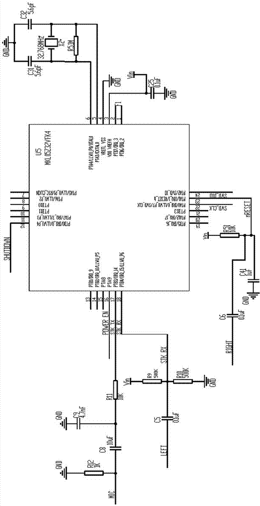
[0030] For the convenience of description, the circuit of the inventive ferromagnetic coating thickness gauge based on the mobile display terminal will be described in detail below in conjunction with the accompanying drawings.

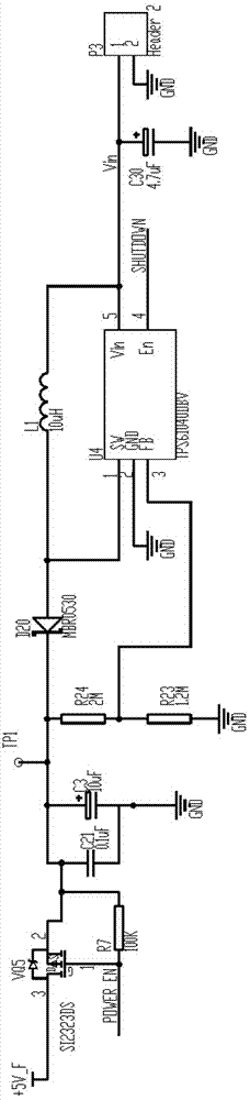
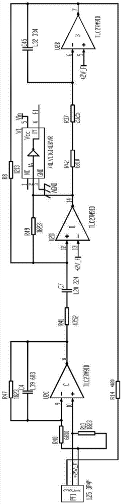
[0031] Such as Figure 1 to Figure 5 As shown in , a ferromagnetic coating thickness gauge circuit based on a mobile display terminal, including F-type coating probe, audio plug, 3-core cable, data acquisition and coding modulation circuit module.

[0032] The data acquisition and coding modulation circuit module includes a data processing circuit.

[0033] In the ferromagnetic coating thickness gauge circuit based on a mobile display terminal, the data processing circuit includes a U5 microcontroller of the model MKL05Z32VFK4, and the U5 microcontroller includes numbers 1 to 24, a total of 24 wiring foot;

[0034] Terminal 1 is PTB6 / IRQ_2, and terminal 1 is connected to F1.

[0035] Pin No. 2 is the PTB7 / IRQ_3 terminal, and pin No. 2 is vacant;

...


PUM


Abstract

The invention provides a ferromagnetic coating thickness gauge circuit based on a mobile display terminal, which includes an F-type coating probe, an audio plug, a 3-core cable, a data acquisition and coding modulation circuit module, and the module includes a data processing circuit , the data processing circuit includes a U5 microcontroller, wherein the No. 5 connecting pin of the U5 microcontroller is the PTA3 / EXTAL0 end, the No. 6 connecting pin is the PTA4 / LLWU_P0 / XTAL0 end, and the No. 5 connecting pin and the No. 6 The connection pins are connected through a resistor R5, and a crystal oscillator X2 is connected in parallel with the resistor R5, and both sides of the crystal oscillator X2 are grounded through a capacitor C31 and a capacitor C32 respectively. The invention has the advantages of improving the use efficiency of mobile terminals and reducing the cost of instruments, which is 40% of the cost of ordinary detectors. The measurement is more accurate, the measurement accuracy is high, the detection error is reduced from ±3% to ±1%, and the degree of automation is higher. Network problems, data backup problems, small size, long life, and the life of the detector equipped with this circuit is increased by 2.5 times.

Description

technical field [0001] The invention relates to the technical field of electrical appliances, in particular to a ferromagnetic coating thickness gauge circuit based on a mobile display terminal. Background technique [0002] The traditional coating thickness gauge adopts the form of a host and a coating probe to form a coating thickness detector. As a professional instrument, this model has been used for decades. But this traditional coating thickness gauge has the following disadvantages: [0003] 1. The display content is not rich enough. The current coating thickness gauges mostly use low-resolution (usually 128*64) FSTN liquid crystal dot matrix. Although some menus and measurement results can be displayed, if the comparative analysis of multiple results is to be carried out, it can only be completed on the computer with the help of PC software, which causes great inconvenience. [0004] 2. It is difficult to implement complex temperature compensation algorithm. Since...

Claims


Application Information

Patent Timeline
Patent Type & Authority Patents(China)
IPC IPC(8): G01B7/06
Inventor 杨庆德尹建华刘宇
Owner 山东中科普锐检测技术有限公司
Why Eureka
Try Eureka