High temperature resistance flowmeter

A technology of high temperature resistance and flowmeter, applied in the field of flowmeter, it can solve the problems of accelerated aging of seal shaft and rubber ring, leakage of medium, inability to realize pipeline transmission, etc., and achieve the effect of avoiding leakage of medium and fast heat dissipation.

Inactive Publication Date: 2015-01-07
成都思达高科软件有限公司
View PDF5 Cites 1 Cited by
  • Summary
  • Abstract
  • Description
  • Claims
  • Application Information

AI Technical Summary

Problems solved by technology

[0002] High-temperature flowmeters are instruments used for measurement in high-temperature environments, such as high-viscosity asphalt and sulfur, and their viscosity is between 100 and 3000mPa.S. Pipeline transmission cannot be realized at room temperature and must be melted before transmission. The first type of high-temperature flowmeter is a magnetic coupling with a seal ring and heat sink connected to the flowmeter; the second type is a mechanically sealed drive shaft with a heat sink connected to the flowmeter; the first type uses a magnetic coupling with heat dissipation The magnet of the magnetic coupling works at high temperature for a long time, there is a problem of demagnetization, the flowmeter will go slower and slower until it stops working, and the magnetic coupling needs to be replaced frequently; the second type of mechanical seal shaft mainly relies on the rubber sealing ring to achieve rotation The shaft seal, working in a high temperature environment for a long time, coupled with the corrosion of the medium, causes the aging of the sealed shaft and rubber ring to accelerate, and the seal ring is quickly damaged, resulting in medium leakage

Method used


Image

  • High temperature resistance flowmeter

Examples


Embodiment Construction

[0013] The present invention will be further explained below in conjunction with the drawings:

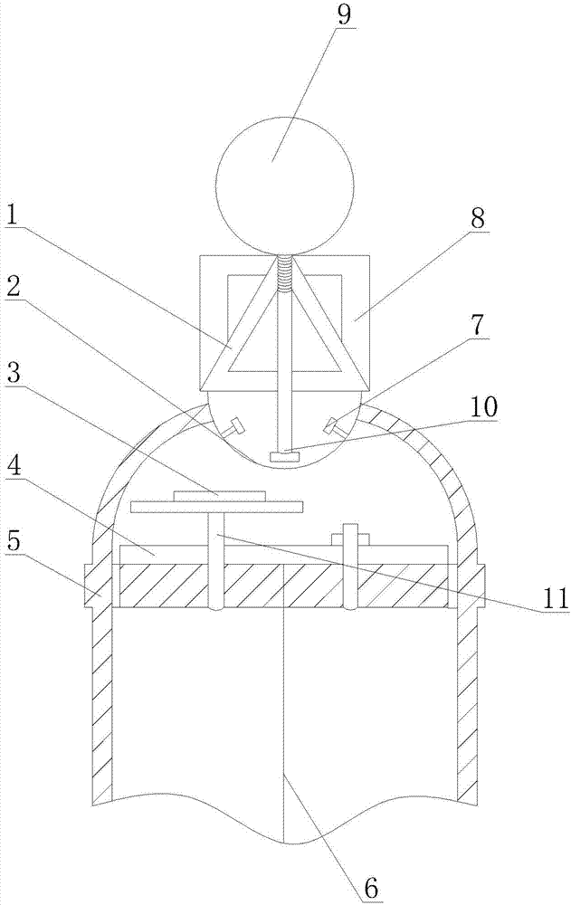
[0014] Such as figure 1 As shown, a high-temperature-resistant flow meter of the present invention includes a bracket 8, a housing 5, a transmitter 3, a high-temperature electromagnetic sensor 10, a rotor wheel 6, a meter head 9, a stabilizer 1, a heat sink 2 and a positioning gear 4 , One end of the rotor wheel 6 is connected to the center of the positioning gear 4, the other end of the rotor wheel 6 is the measuring end of the flow meter, a connecting frame 11 is fixed on the positioning gear 4, and the signal transmitter 3 is arranged on the top surface of the connecting frame 11. The rotor wheel 6 and the positioning gear 4 are both located in the housing 5. The top surface of the housing 5 is provided with a through hole, one end of the heat dissipation cylinder 2 is located in the housing 5, and the other end of the heat dissipation cylinder 2 is connected to the bottom surface ...


PUM


Abstract

The invention discloses a high temperature resistance flowmeter, and the high temperature resistance flowmeter comprises a bracket, a shell, a pinger, a high temperature resistance electromagnetic sensor, a rotor wheel, a header, a stable shelf, a heat dissipation tube and a locating gear, one end of the rotor wheel is connected to the centre of the locating gear while the other end is the measuring end of the flowmeter, a connection shelf is fixed on the locating gear, the pinger is formed at the top side of the connection shelf, the rotor wheel and the locating gear are located in the shell, one end of the heat dissipation tube is located in the shell while the other end is connected to the underside of the bracket, the signal output end of the high temperature resistance electromagnetic sensor is connected to the header through the wire and the signal collecting end of the high temperature resistance electromagnetic sensor is located in the heat dissipation tube in the shell not contacting the heat dissipation tube, a plurality of mini fans are formed in the heat dissipation tube. The high temperature resistance electromagnetic sensor does not contact the bottom of the heat dissipation tube, so the outer temperature and the inner temperature of the heat dissipation tube can have heat loss through convection, the mini fans speeds up the air convection, so the heat dissipation speed is faster.

Description

Technical field [0001] The invention relates to a flow meter, in particular to a high temperature resistant flow meter. Background technique [0002] High-temperature flow meters are instruments used for measurement in high-temperature environments, such as high-viscosity asphalt and sulfur. Their viscosity is between 100 and 3000mPa.S. Pipeline transmission cannot be achieved at room temperature. It must be melted before transmission. There are currently two The first type of high-temperature flowmeter is to connect the flowmeter with a magnetic coupling plus a sealing ring and a heat sink. The second type is to use a mechanically sealed drive shaft and a heat sink to connect the flowmeter. The first type uses a magnetic coupling with heat dissipation. The magnet of the magnetic coupling has been working at high temperature for a long time, and there is a problem of demagnetization. The flowmeter will go slower and slower until it stops working. The magnetic coupling needs to be...

Claims


Application Information

Patent Timeline
Patent Type & Authority Applications(China)
IPC IPC(8): G01F1/74G01F15/18
Inventor 何栋杰徐科
Owner 成都思达高科软件有限公司
Why Eureka
Try Eureka