Minisize fluid forced convection device

A forced convection, miniature technology, used in sampling devices, liquid degassing, preparation of test samples, etc., can solve the problems of poor convection, complicated installation, damage, etc., and achieve the effect of reducing response time, simple structure and reliable performance

Inactive Publication Date: 2010-05-26
ASENSOR TECH
View PDF9 Cites 0 Cited by
  • Summary
  • Abstract
  • Description
  • Claims
  • Application Information

AI Technical Summary

Problems solved by technology

The advantage of this method and device is that there is no need for an oil pump, so the reliability is good; but the disadvantage is that when the distance between the monitored equipment body such as the transformer main oil tank and the gas monitoring device is long, for example, when the distance is greater than 6 times the diameter of the oil pipe or valve , the convection of the oil sample is unsatisfactory, that is to say, in this case, two problems will arise: the first is that the oil sample near the gas monitoring device is not uniform, and the second is that it will prolong the response time of the gas monitoring device
But there are still two problems in this method, one is that the moving slide bar in the device can only pass through the straight-through valve (that is, when the valve is opened, there is no hindrance on both sides of the valve), such as figure 1 The valve 32a in is a straight-through valve; but it is not applicable to non-straight-through valves (also known as cut-off valves) commonly used in transformers, such as figure 2 The valve 32b in is a non-straight-through valve. When the valve is opened, both sides of the valve are connected through a "Z"-shaped bend; secondly, because the separate external oil pump is used, that is, the oil pump independent of the transformer valve, it will still be Limited by the reliability of valves, pipelines, joints and the oil pump itself
[0007] In addition, the above-mentioned external oil pump solution is not only complicated to install, but also the pipeline is affected by the external harsh environment such as the change of ambient temperature after installation. For example, when the ambient temperature is low, an additional heater must be installed inside or outside the pipeline to prevent high Viscosity of the oil damages the oil pump

Method used


Image

  • Minisize fluid forced convection device
  • Minisize fluid forced convection device
  • Minisize fluid forced convection device

Examples


Embodiment Construction

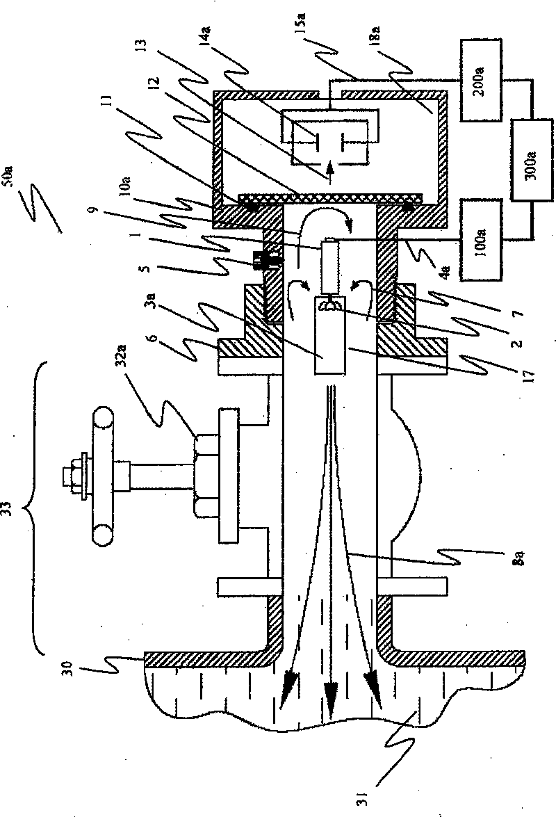
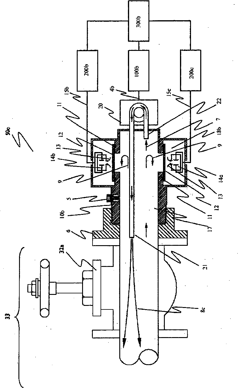
[0019] Such as Figure 1 to Figure 3 Shown are three preferred embodiments of the invention, in figure 1 with image 3 Among them, the straight-through valve 32a is installed in the transformer main oil tank 30 ( image 3 (not marked in), the total length of the oil pipe 33 between the main oil tank 30 and the valve 32a is greater than or equal to 6 times the inner diameter of the valve 32a, or the total length is greater than 200mm. When the valve 32a is fully opened, the transformer oil 31 in the main oil tank 30 can flow directly to the outside of the valve horizontally.

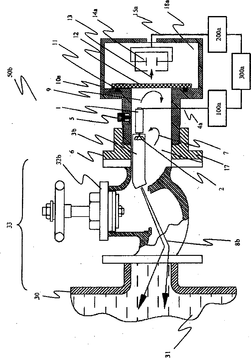
[0020] exist figure 2 Among them, the non-straight-through valve 32b is installed on the main oil tank 30 of the transformer. When the valve 32b is fully opened, the transformer oil 31 in the main oil tank 30 will communicate with the outside of the valve through a "Z" shaped channel.

[0021] from Figure 1 to Figure 3 It can be seen from the figure that the fluid forced convection devices 50a, 50...


PUM

PropertyMeasurementUnit
diameteraaaaaaaaaa

Abstract

The invention relates to a miniature fluid forced convection device for the on-line monitoring of electrical equipment, which comprises an integral joint. A convection cavity communicated with the outlet of a valve is arranged in the integral joint, an air exhaust / oil bleeding unit is arranged above the convection cavity, and an air exhaust / oil bleeding bolt capable of being screwed up or loosened, a rubber seal ring and an air exhaust / oil bleeding outlet are arranged in the air exhaust / oil bleeding unit. A test cavity for containing a gas testing unit is communicated with the convection cavity and is arranged in the integral joint, and an oil-gas separation film is arranged between the convection cavity and the test cavity. A convection drive unit capable of driving insulating oil to carry out forced convection between the oil tank of the electrical equipment and the convection cavity of the integral joint through the valve is arranged in the convection cavity. The convection drive unit can be the combination of a miniature motor, a miniature propulsion propeller and a duct, or the combination of an oil inlet pipe, an oil outlet pipe and an external miniature oil pump. The invention provides a device capable of realizing the integration of inside and outside sample oil forced convection and on-line monitoring on the valve of individual equipment.

Description

technical field [0001] The present invention relates to the technology of on-line monitoring of high-voltage electrical equipment, and more specifically, relates to a forced convection device used for insulating fluid of high-voltage electrical equipment between the interior of the equipment body and the external online monitoring device connected thereto. It can be used in electrical equipment such as transformers to ensure sufficient convection between the oil sample inside the equipment and the oil sample outside the connected valve to ensure the effectiveness and timeliness of the results of the online monitoring device. Background technique [0002] In oil-immersed high-voltage electrical equipment, such as transformers, insulating oil is usually used as a dielectric and heat dissipation medium, but insulating oil also has a very important role, that is, as a carrier of fault gas. As we all know, when there is abnormal overheating or partial discharge inside the high-vo...

Claims


Application Information

Patent Timeline
Patent Type & Authority Patents(China)
IPC IPC(8): G01N1/10G01N1/38B01D19/00
Inventor 秦仁炎
Owner ASENSOR TECH
Why Eureka
Try Eureka