Detection method of dynamic light scattering particle detection device

A technology of dynamic light scattering and particle detection, which is applied to measuring devices, particle and sedimentation analysis, particle size analysis, etc. It can solve the problems of large measuring devices, easy to be dusted, and low signal-to-noise ratio, and achieve flexible and improved measuring devices. Signal-to-noise ratio, overcome the effect of large volume

Inactive Publication Date: 2017-01-18
SHANDONG UNIV OF TECH
View PDF6 Cites 0 Cited by
  • Summary
  • Abstract
  • Description
  • Claims
  • Application Information

AI Technical Summary

Problems solved by technology

[0004] However, the optical path of the traditional dynamic light scattering device is usually composed of a series of optical devices placed outside the sample cell, such as lenses and pinholes, resulting in a large volume of the entire measurement device; and because the scattered light is transmitted in the air, it is easily affected by dust, The interference of external light and vibration causes the signal-to-noise ratio of the system to be low, and the quality of the correlation function output by the photon correlator is degraded, so that reliable measurement results cannot be obtained. As a result, the traditional dynamic light scattering device is only suitable for laboratories and cannot For industrial online measurement

Method used


Image

  • Detection method of dynamic light scattering particle detection device
  • Detection method of dynamic light scattering particle detection device
  • Detection method of dynamic light scattering particle detection device

Examples


Embodiment Construction

[0038] Figure 1-12 It is the best embodiment of the present invention. Figure 1-12 The present invention will be further explained.

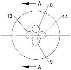
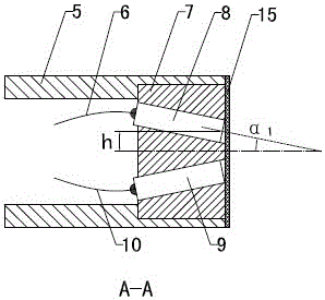
[0039] Reference attached figure 1 :Dynamic light scattering particle measurement integrated optical fiber probe, including outer casing 5 and optical fiber. The outer casing 5 can be a stainless steel casing with a hollow interior. The optical fiber can be a single-mode polarization maintaining fiber. One end of the optical fiber is installed in the inner cavity of the outer casing 5. , The other end of the optical fiber passes out of the outer shell 5, and the optical fiber includes a transmitting fiber and a receiving fiber; one end of the outer shell 5 is a closed end and the other end is an open end. The fixed disc 7 is tightly installed at the open end, and the fixed disc 7 is built in The self-focusing lens is fixedly installed in the through hole, and the pitch of the self-focusing lens is 0.25. The self-focusing lens includes a transmitti...


PUM


Abstract

A detection method of a dynamic light scattering particle detection device belongs to the technical field of dynamic light scattering nano particle measurement devices. It is characterized in that: the optical fiber probe includes a transmitting optical fiber and a receiving optical fiber; one end of the outer shell of the optical fiber probe (5) is a closed end, and the other end is an open end, and a fixed disc (7) is tightly installed on the open end, and through the fixed disc (7) The built-in through hole fixes the self-focusing lens. The self-focusing lens includes a transmitting lens and a receiving lens. The inner ends of the transmitting lens and the receiving lens are respectively connected to the transmitting optical fiber and the receiving optical fiber. The invention changes the optical path of the traditional dynamic light scattering device, introduces the optical fiber into the dynamic light scattering technology, uses the optical fiber to integrate the emitting optical path and the receiving optical path, can measure high-concentration samples, and can realize on-line detection in industrial production.

Description

Technical field [0001] The detection method of the dynamic light scattering particle detection device belongs to the technical field of dynamic light scattering nano particle detection device. Background technique [0002] The size and distribution of submicron and nano particles are the main parameters that characterize their performance, so the measurement of these parameters is of great significance. Dynamic light scattering technology is an effective method for submicron and nanometer particle size measurement. [0003] In the dynamic light scattering particle measurement technology, photon correlation spectroscopy is widely used, which uses a photomultiplier tube to receive scattered light at a fixed spatial position. Because the scattered light is extremely weak, the photomultiplier tube can only receive discrete photon pulses, and at the same time output corresponding electrical pulses at the output end, and send the pulse signals to the photon correlator. After the photon...

Claims


Application Information

Patent Timeline
Patent Type & Authority Patents(China)
IPC IPC(8): G01N15/02
Inventor 刘伟马立修陈文钢张珊珊
Owner SHANDONG UNIV OF TECH
Why Eureka
Try Eureka