Method for positioning constructed wetland blocked region through composite profiling apparent resistivity curves

A technology combining profile and apparent resistivity, applied in the field of sewage treatment to achieve efficient operation

Inactive Publication Date: 2015-01-07
GUILIN UNIVERSITY OF TECHNOLOGY
View PDF4 Cites 25 Cited by
  • Summary
  • Abstract
  • Description
  • Claims
  • Application Information

AI Technical Summary

Problems solved by technology

[0006] The purpose of the present invention is to solve the clogging problem in constructed wetlands, and provide a metho

Method used


Image

  • Method for positioning constructed wetland blocked region through composite profiling apparent resistivity curves
  • Method for positioning constructed wetland blocked region through composite profiling apparent resistivity curves
  • Method for positioning constructed wetland blocked region through composite profiling apparent resistivity curves

Examples


Embodiment 1

[0029] Constructed wetland without clogging combined with cross-sectional apparent resistivity measurement.

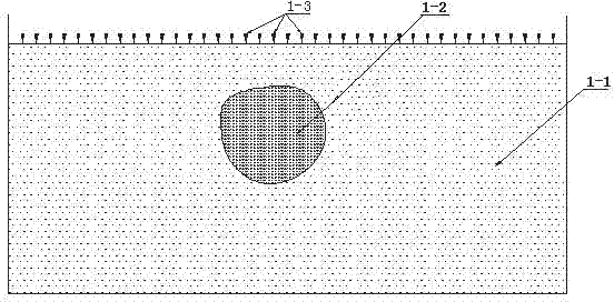
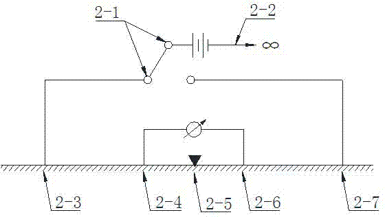
[0030] (1) if figure 1 , 2 As shown, firstly, the joint profile device is arranged at the electrode layout point 1-3 of the laid joint profile survey line for measurement, the distance between the measuring electrode M2-4 and the measuring electrode N2-6 is 10 cm, and the positive pole of the power supply electrode is A pole 2-3 and The B pole 2-7, the negative electrode of the power supply electrode is the C pole 2-2 of "infinity".

[0031] (2) Arrange the "infinity" C pole 2-2, the C pole is arranged perpendicular to the direction of the survey line, and the distance from the survey line is 200cm.

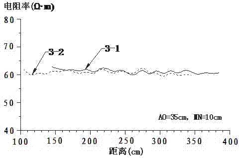
[0032](3) Arrange A pole 2-3 and B pole 2-7 according to AO=35cm (filling depth of constructed wetland example is about 100cm). Observe twice, one time is AMN device, the positive pole of the power supply is connected to the A pole 2-3, and the negative pole of the pow...

Embodiment 2

[0037] Combined section apparent resistivity measurement of constructed wetlands with clogged areas.

[0038] (1) if figure 1 , 2 As shown, firstly, the joint profile device is arranged at the electrode layout point 1-3 of the laid joint profile survey line for measurement, the distance between the measuring electrode M2-4 and the measuring electrode N2-6 is 10 cm, and the positive pole of the power supply electrode is A pole 2-3 and The B pole 2-7, the negative electrode of the power supply electrode is the C pole 2-2 of "infinity".

[0039] (2) Arrange the "infinity" C pole 2-2. The C pole should be arranged perpendicular to the direction of the survey line, and the distance from the survey line should be 200cm.

[0040] (3) Arrange A pole 2-3 and B pole 2-7 according to AO=35cm (filling depth of constructed wetland example is about 100cm). Observe twice, one time is AMN device, the positive pole of the power supply is connected to the A pole 2-3, and the negative pole of...


PUM


Abstract

The invention discloses a method for positioning a constructed wetland blocked region through composite profiling apparent resistivity curves. A composite profiling apparent resistivity measuring device is arranged on a constructed wetland and performs measuring point by point in an apparent resistivity profiling mode, a power supply positive electrode A, a power supply positive electrode B, a measuring electrode M and a measuring electrode N of the measuring device are arranged symmetrical about a measuring point O, measuring is performed between A and O by the selection of two electrode distances, and an 'infinitely distant' electrode C is arranged perpendicular to the measuring line. A measured apparent resistivity pAS and a measured apparent resistivity pBS which are obtained according to AO=H/3 and AO=H are used for drawing the composite profiling apparent resistivity curves in a full line and an imagery line respectively. If the measuring line is blocked, the composite profiling apparent resistivity curves will have the characteristic of a high-resistance negative intersection point, and the transverse position of the blocked region can be determined according to the position of the high-resistance negative intersection point; according to the characteristics of the apparent resistivity curves of the two electrode distances, the longitudinal distribution position of the blocked region is roughly judged, and namely the spatial distribution of the blocked region on the measuring line is determined.

Description

technical field [0001] The invention belongs to the technical field of sewage treatment, and in particular relates to a method for locating clogged areas of constructed wetlands by using combined section apparent resistivity curves. Background technique [0002] Constructed wetland sewage treatment technology is a new ecological engineering technology for sewage treatment that emerged in the 1970s. It has the advantages of good flexibility, low investment, low energy consumption, strong decontamination ability, convenient management, and no secondary pollution. Applications are increasingly common. However, in recent years, problems such as clogging frequently occur in constructed wetlands during operation, the purification performance decreases, and the service life is shortened. For example, among the 355 subsurface flow constructed wetlands in the United States and the United Kingdom, nearly half of them were blocked within five years of use, and the hydraulic conductivi...

Claims


Application Information

Patent Timeline
IPC IPC(8): G01V3/04
Inventor 丁彦礼白少元解庆林
Owner GUILIN UNIVERSITY OF TECHNOLOGY
Why Eureka
Try Eureka