
Optical fiber terminal fixing tool for winding optical fiber and optical fiber winding method

A technology of optical fiber terminal and fixing parts, which is applied in the field of optical fiber terminal fixing parts to achieve the effect of improving efficiency

Active Publication Date: 2015-01-14
FUJIKURA LTD
View PDF7 Cites 12 Cited by
  • Summary
  • Abstract
  • Description
  • Claims
  • Application Information

AI Technical Summary

Problems solved by technology

However, even if the bobbin has only one winding portion, if the width of the winding portion is extremely narrow, the same problems as above may occur.

Method used


Image

  • Optical fiber terminal fixing tool for winding optical fiber and optical fiber winding method
  • Optical fiber terminal fixing tool for winding optical fiber and optical fiber winding method
  • Optical fiber terminal fixing tool for winding optical fiber and optical fiber winding method

Examples


Embodiment Construction

[0070] Hereinafter, embodiments of the present invention will be described in detail.

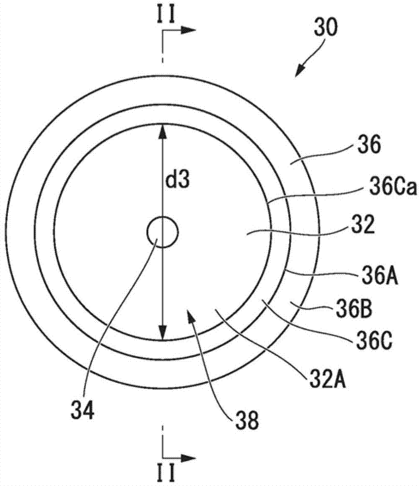
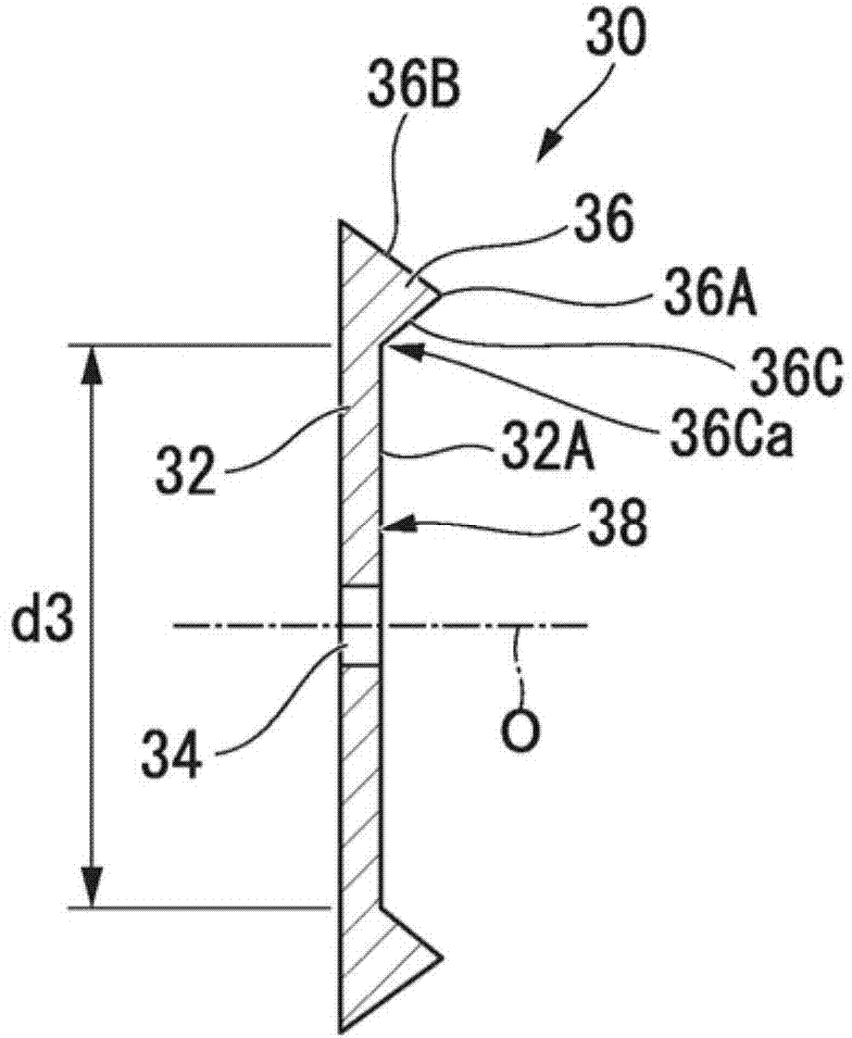
[0071] figure 1 , figure 2 The overall structure of the optical fiber terminal fixture according to the embodiment of the present invention is shown.

[0072] exist figure 1 , figure 2 Among them, the optical fiber terminal fixing member 30 is made of, for example, relatively hard resin such as ABS resin or metal such as aluminum, and is composed of a disc-shaped base (disk-shaped base) 32 as a whole. A shaft hole 34 through which a rotating shaft of a winding machine (not shown) is inserted is formed in a central portion of the disk-shaped base 32 so as to penetrate along the central axis O. As shown in FIG. In addition, an annular raised portion 36 protruding in a direction parallel to the central axis O is formed on a portion of one disk surface 32A of the disk-shaped base 32 near the outer peripheral edge.

[0073] The raised portion 36 is continuous along the circumferential d...


PUM


Abstract

An optical fiber terminal fixing tool includes: a disc-shaped substrate having a plate surface; a holding surface which is provided on the plate surface and interposes the terminal portion of the optical fiber between the holding surface and the first flange portion; and a protrusion which continues in a circumferential direction with a larger diameter than an outer diameter of the first flange portion in an outer circumferential portion on the plate surface while protruding toward the bobbin in a state where the fixing tool is mounted on the rotating shaft of the optical fiber winding machine.

Description

[0001] This application claims the priority of Japanese Patent Application No. 2013-138935 for which it applied on July 2, 2013, and uses the content here. technical field [0002] The present invention relates to an optical fiber terminal fixture for winding an optical fiber around a flange portion of an optical fiber winding bobbin having a flange portion and a method for winding an optical fiber around a bobbin using the same During the winding section between the fibers, the bobbin is fixed to the end of the optical fiber at the beginning of winding. In particular, the present invention relates to an optical fiber terminal fixing member preferably used for guiding an optical fiber whose terminal has been fixed to a bobbin to a winding portion, and a winding method using the same. Background technique [0003] In the manufacturing process of the optical fiber wire harness, the manufacturing process of the optical fiber core wire, etc., the optical fiber wire bundle or the...

Claims


Application Information

Patent Timeline
Patent Type & Authority Applications(China)
IPC IPC(8): B65H65/00B65H54/02
CPCG02B6/4457B65H54/00B65H65/00B65H2701/32
Inventor 赤松毅史
Owner FUJIKURA LTD
Learn More