
Torque Transmission Mechanism

A technology of torque transmission mechanism and starting torque, which is applied in the direction of mechanical equipment, engine components, machines/engines, etc., and can solve problems such as increasing sealing gaskets and lubricant leakage

Inactive Publication Date: 2015-01-14
AB SKF
View PDF1 Cites 0 Cited by
  • Summary
  • Abstract
  • Description
  • Claims
  • Application Information

AI Technical Summary

Problems solved by technology

Known techniques do not solve this problem and accept some lubricant leakage, or simply add sealing gaskets

Method used


Image

  • Torque Transmission Mechanism
  • Torque Transmission Mechanism
  • Torque Transmission Mechanism

Examples


Embodiment Construction

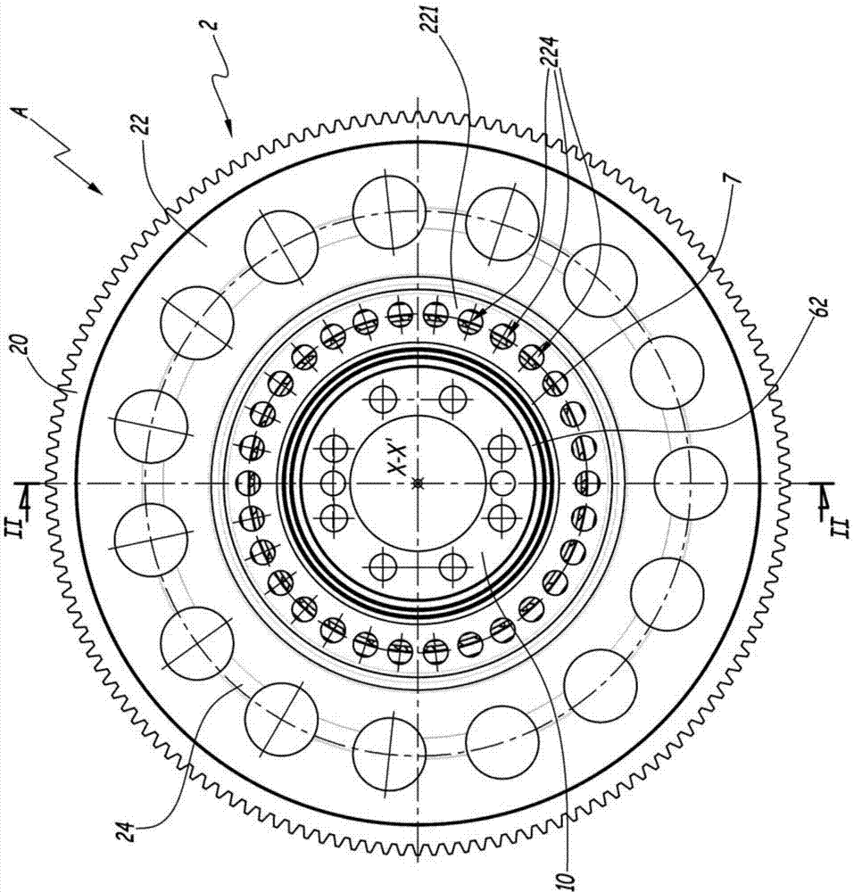
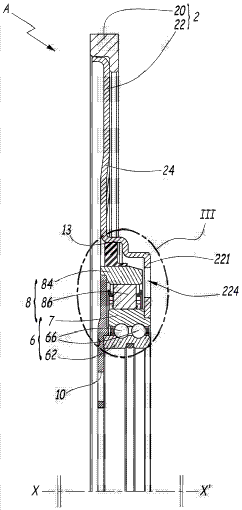
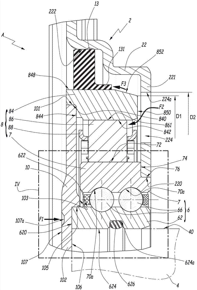
[0022] pictured in Figures 1 to 7 The torque-transmitting mechanism A in includes a ring gear 2 driven by a not-shown pinion of a not-shown starter motor. The ring gear 2 is rotatable relative to a crankshaft 4 of a not shown internal combustion engine. For simplicity and clarity, axis 4 is only in image 3 and 4 Shown above with a dotted line. The rotation of the ring gear 2 relative to the crankshaft 4 is allowed by means of a rolling bearing 6 comprising an inner ring 62 adapted to receive the crankshaft 4 and connected in rotation with it; Two raceways 70a, the tubular portion 7 is rotationally connected with the ring gear 2; and rolling elements, such as balls 66, between the inner ring 62 and the raceway 70a.

[0023] The torque transmitting mechanism A also includes a one-way clutch 8 comprising an inner ring formed by the outer surface 72 of the tubular portion 7, an outer ring 84 and mounted in a cage 88 between the inner ring 82 and the outer surface 72. Wedge ...


PUM


Abstract

This torque transmission mechanism (A) for an internal combustion engine, adapted to transmit a starting torque from a starter motor to a crankshaft (4) of the internal combustion engine, comprises a ring gear (2) that transmits the starting torque, a one-way clutch (8) disposed between the ring gear (2) and the crankshaft (4), a bearing (6) including a first ring (7) coupled in rotation with the gear ring (2) and a second ring (62) coupled in rotation with the crankshaft (4) and a front plate (10) for coupling in rotation the crankshaft (4) with the one-way clutch (8). The front plate (10) is coupled in rotation with the crankshaft (4) via the second ring (62) of the bearing (6), by welding along a direction (F1) parallel to a central axis (X-X') of the second ring (62) of the bearing (6).

Description

technical field [0001] The invention relates to a torque transmitting mechanism for an internal combustion engine. Background technique [0002] On torque-transmitting mechanisms for starter motors of internal combustion engines, the mechanism often includes a front plate, which forms the outer race of a one-way clutch and is connected in rotation with the crankshaft of the internal combustion engine. This mechanism generally includes a bearing arrangement comprising an inner ring rotatably connected to the front plate and the crankshaft. It is known to attach the inner ring of the bearing to the front plate by providing a shoulder on the crankshaft so that the inner ring of the bearing stops between said shoulder and the front plate. This technique is unsatisfactory. [0003] Lubricant for the torque transmitting mechanism may leak through holes between the front plate and components of the mechanism. Known techniques do not solve this problem and accept some lubricant l...

Claims


Application Information

Patent Timeline
Patent Type & Authority Applications(China)
IPC IPC(8): F02N15/02
CPCF01D11/00F16C19/00F02N15/023F02N2250/08F02N15/022F02N15/006F16C19/08F16C35/06F16C2226/36F16D41/07F16D41/00F16H55/17
Inventor C.钱邦尼奥N.伯鲁特F.钱帕洛P.里鲍尔特Y-A.利夫拉托R.科比特N.休恩
Owner AB SKF
Learn More