
Method for testing material heat conductivity coefficient through transient plane heat source method

A plane heat source method and thermal conductivity technology, applied in the direction of material thermal development, etc., can solve the problems that cannot accurately reflect the properties of materials, cannot accurately reflect the research process, and the measurement results of thermal conductivity are incorrect.

Inactive Publication Date: 2015-01-14
北京中建建筑科学研究院有限公司 +1
View PDF3 Cites 18 Cited by
  • Summary
  • Abstract
  • Description
  • Claims
  • Application Information

AI Technical Summary

Problems solved by technology

The steady-state method has the advantages of clear principle, simple model, accurate and direct acquisition of the absolute value of thermal conductivity, etc., and is suitable for the measurement of a wide temperature range; the disadvantage is that the experimental conditions are harsh and the measurement time is long; in the steady-state method, in order to To obtain accurate heat flow, it is necessary to strictly ensure the adiabatic condition of the test system, attach a compensation heater and increase insulation measures to reduce edge heat loss; in addition, the steady-state method is mainly used to measure the thermal conductivity of solid materials, and it should be used for It is very difficult to study wet materials, because the moisture content of the sample will change due to the long-term maintenance of a certain temperature field, which will lead to incorrect measurement results of thermal conductivity
[0004] With the development of new materials, the requirements for testing speed are greatly increased, and because of the diversity of new materials, the parameters obtained by traditional methods cannot accurately reflect the properties of materials, and the traditional models cannot accurately reflect the process to be studied, so Transient method is widely used

Method used


Image

  • Method for testing material heat conductivity coefficient through transient plane heat source method
  • Method for testing material heat conductivity coefficient through transient plane heat source method
  • Method for testing material heat conductivity coefficient through transient plane heat source method

Examples


Embodiment Construction

[0015] The present invention will be further described in detail according to the examples below.

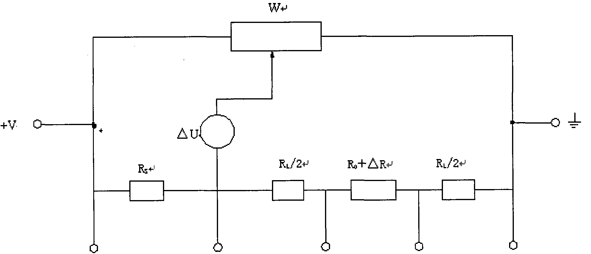
[0016] Balanced bridge: The voltage used for the balanced bridge should make the system current not greater than 1mA, and the reading of the digital voltmeter of the bridge test system is zero after the bridge is balanced.

[0017] Apply heat pulse: According to the total test time and output power, apply a constant direct current to the probe to generate a heat pulse in the sample, and divide the voltage at the initial moment of transient heating by testing the total resistance of the bridge system (that is, R s +R L +R o ), get the current I0 passing through the probe at this time, and the sliding contact of the potentiometer should not be adjusted during this test.

[0018] Acquisition of unbalanced voltage: within the total test time, scan and record the unbalanced voltage at an appropriate time interval, that is, the potential change △U, and the number of acquisitions sho...


PUM

PropertyMeasurementUnit
Thicknessaaaaaaaaaa
Diameteraaaaaaaaaa

Abstract

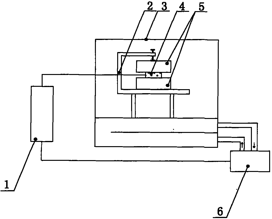
The invention relates to a method for testing a material heat conductivity coefficient through a transient plane heat source method; the method is achieved through a testing device, and the testing device mainly comprises a probe, an electrical bridge testing system, and a data acquisition and analysis system; in the electrical bridge testing system, a power supply for supplying power for an electrical bridge is regulated in the range of 0-20 V, and the maximum current does not exceed 1 A. The method can measure various samples such as bulk samples, uniaxial anisotropic samples, thin sheet samples and thin film samples, and is high in control accuracy, short in detection period, and accurate in testing results.

Description

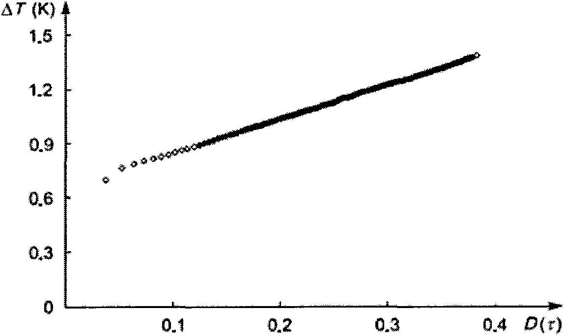
technical field [0001] The invention belongs to the field of material performance detection, and mainly uses a plane heat source test method to detect the thermal conductivity and thermal diffusivity of building materials. The specific method is to place the probe between two samples and apply a constant direct current to the probe. After the probe is exothermic, a dynamic temperature field will be generated inside the sample, and at the same time, the temperature of the probe surface will rise. At this time, the resistance of the probe will increase, so that the original balance of the bridge test system The bridge is unbalanced, resulting in a change in potential. By recording the variation of electrical parameters at different times during the test, the function of the temperature increase over time is calculated. The thermal conductivity and thermal diffusivity of the sample are obtained by fitting and calculating the function curve. Background technique [0002] Therm...

Claims


Application Information

Patent Timeline
IPC IPC(8): G01N25/20
Inventor 任静张金花段恺王永艳崔新阳朱剑飞
Owner 北京中建建筑科学研究院有限公司
Learn More