Microwave oven power detection method and system
A voltage detection method and microwave oven technology, which are applied in power supply testing, measuring devices, measuring electrical variables, etc., can solve the problems of reduced detection accuracy, increased cost, and reduced safety, so as to improve the safety of use, real-time accurate detection, and reduce cost effect
- Summary
- Abstract
- Description
- Claims
- Application Information
AI Technical Summary
Problems solved by technology
Method used
Image

Examples
Embodiment 1
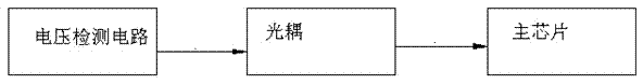
[0022] Such as figure 1 As shown, a voltage detection method for a microwave oven includes a voltage detection circuit, a photocoupler and a main chip, the input terminal of the voltage detection circuit is connected to the strong current circuit, and the output terminal of the voltage detection circuit is connected to the input terminal of the photocoupler. The output end of the photocoupler is connected with the input end of the main chip. The voltage detection circuit samples from the strong current circuit, and transmits the real-time sampling results to the voltage detection chip for processing. The voltage detection chip determines whether the current voltage value exceeds the preset normal use voltage range of the equipment. If it is within the preset If it is within the normal voltage range, the microwave oven operates normally; if it exceeds the normal range, continue to judge whether the current voltage value exceeds the preset voltage range or is lower than the pres...
Embodiment 2
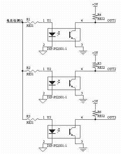
[0024] Such as figure 2 As shown, a detection system of a microwave oven voltage detection method includes three photocoupler circuits connected in parallel with the strong current circuit, each photocoupler circuit is composed of a photocoupler and two resistors, and the photocoupler has a light-emitting a diode and a phototransistor for converting the light signal emitted by the light emitting diode into an electrical signal. The emitter of the first photocoupler U1 is grounded, and its collector is divided into two circuits, one of which is connected to the high level through the first resistor R4, and the other is connected to the main chip, and the output terminal of the external strong current signal source is connected to the luminous The diode is electrically connected; the emitter of the second photocoupler U2 is grounded, and its collector is divided into two circuits, one of which is connected to the high level through the second resistor R5, and the other is conne...
PUM
 Abstract
Description
Claims
Application Information
 - R&D
- Intellectual Property
- Life Sciences
- Materials
- Tech Scout
- Unparalleled Data Quality
- Higher Quality Content
- 60% Fewer Hallucinations
Browse by: Latest US Patents, China's latest patents, Technical Efficacy Thesaurus, Application Domain, Technology Topic, Popular Technical Reports.
© 2025 PatSnap. All rights reserved.Legal|Privacy policy|Modern Slavery Act Transparency Statement|Sitemap|About US| Contact US: help@patsnap.com