non-volatile semiconductor storage device
A storage device and non-volatile technology, applied in the field of non-volatile semiconductor storage devices, can solve problems such as data changes, and achieve the effect of high data retention characteristics
- Summary
- Abstract
- Description
- Claims
- Application Information
AI Technical Summary
Problems solved by technology
Method used
Image
Examples
no. 1 example
[0026] First, the overall configuration of the nonvolatile semiconductor memory device according to the first embodiment will be described.
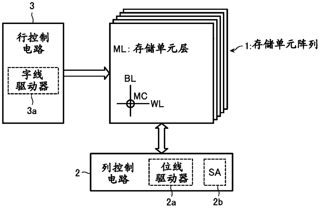
[0027] figure 1 is a block diagram showing the overall configuration of the nonvolatile semiconductor memory device according to the present embodiment.
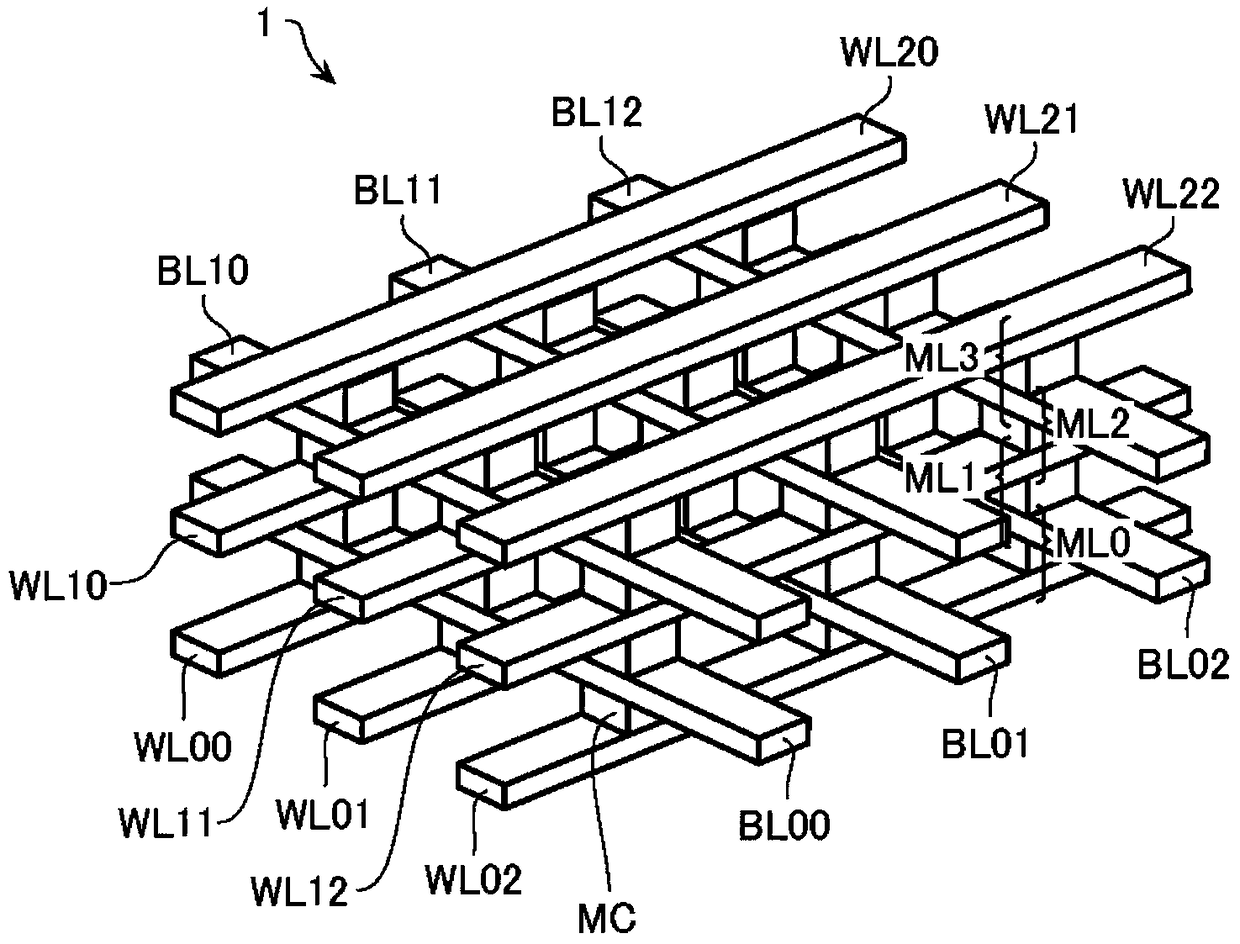
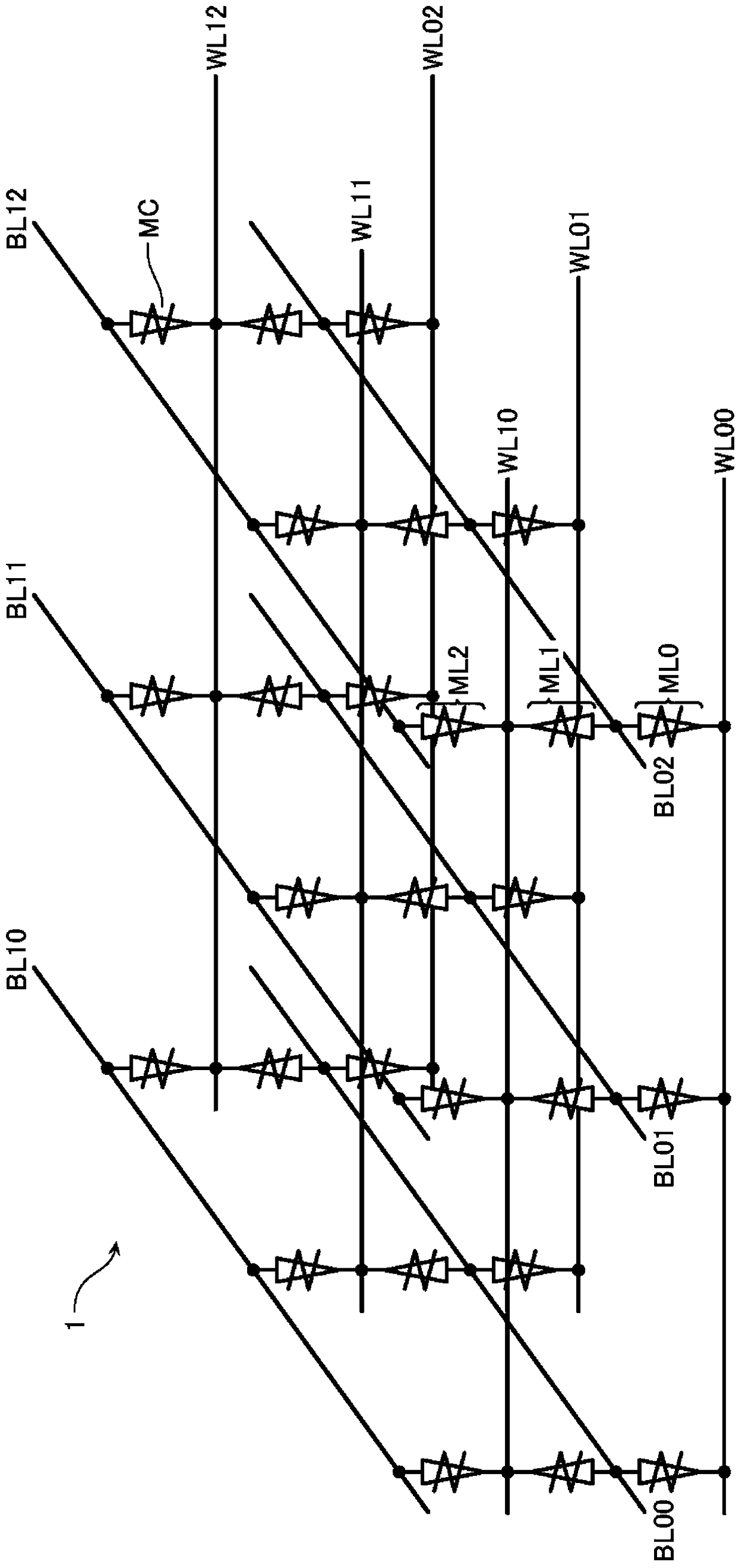
[0028] The nonvolatile semiconductor memory device includes a memory cell array 1 , a column control circuit 2 and a row control circuit 3 that control data erasing, data writing, and data reading with respect to the memory cell array 1 . The memory cell array 1 includes a plurality of stacked memory cell layers ML. Each memory cell layer ML includes a plurality of bit lines BL (first lines) and a plurality of word lines WL (second lines) intersecting each other, and memory cells MC connected to respective intersections of these bit lines BL and word lines WL . It should be pointed out below that data erasing, data writing and data reading with respect to the memory cell array 1 or ...
no. 2 example
[0076] The second embodiment describes a different writing sequence than the first embodiment.
[0077] Figure 10 is a graph showing voltages applied to memory cells during a write sequence of the nonvolatile semiconductor memory device according to the second embodiment. It should be pointed out that Figure 10 The pulse indicated by the dash / double-dot dash line in is the reset pulse ( Figure 10 Shown as "reset"), the reset pulse has the height of the reset voltage Vreset required for the reset operation. It should be noted that the reset pulse is indicated for reference and is not actually applied to the memory cell MC during the write sequence.
[0078] First, in step S201, a removal step is performed. This removal step is similar to that in step S103 in the first embodiment. As a result, only weakly coupled metal atoms included in the fibrils that have been formed by the previous writing sequence or the like are pulled back to the metal layer 11 .
[0079] Then, i...
no. 3 example
[0085] The third embodiment describes a writing sequence different from that of the first and second embodiments.
[0086] Figure 11 is a diagram showing voltages applied to memory cells during a write sequence of the nonvolatile semiconductor memory device according to the third embodiment. It should be pointed out that Figure 11 The pulse indicated by the dash / double-dot dash line in is the reset pulse ( Figure 11 Shown as "reset"), the reset pulse has the height of the reset voltage Vreset required for the reset operation. It should be noted that the reset pulse is indicated for reference and is not actually applied to the memory cell MC during the write sequence.
[0087] First, in step S301, a setting step is performed. This setting step is similar to that in step S101 in the first embodiment. This step results in elongation of the fibrils in the ion-conducting layer 12 .
[0088] Then, in step S302, a removal step is performed. This removal step is similar to t...
PUM
 Abstract
Description
Claims
Application Information
 - R&D
- Intellectual Property
- Life Sciences
- Materials
- Tech Scout
- Unparalleled Data Quality
- Higher Quality Content
- 60% Fewer Hallucinations
Browse by: Latest US Patents, China's latest patents, Technical Efficacy Thesaurus, Application Domain, Technology Topic, Popular Technical Reports.
© 2025 PatSnap. All rights reserved.Legal|Privacy policy|Modern Slavery Act Transparency Statement|Sitemap|About US| Contact US: help@patsnap.com


