Method and device for configuring boundary frequency band of efficient filter rapidly

A fast configuration and filter technology, applied in impedance networks, digital technology networks, electrical components, etc., can solve the problems of many design steps, insufficient consideration, and difficulty in application, and achieve excellent stopband attenuation, small passband ripple, and resistance. With a large attenuation effect

Inactive Publication Date: 2015-01-14
TIANJIN UNIV
View PDF4 Cites 12 Cited by
  • Summary
  • Abstract
  • Description
  • Claims
  • Application Information

AI Technical Summary

Problems solved by technology

[0004] However, the disadvantages of the method in literature [10] are: (1) The method has many steps, and the closed analytical expression of the final filter coefficient is not deduced, so it is difficult to apply to the occasion where the hardware configuration of the filter coefficient needs to be done quickly
This is because each step of the method in literature [10] is based on the all-phase filter design method, and the design of its prototype filter and compensation filter must follow the general process of the all-phase filter design method (specifically, the design The method needs to do IDFT, coefficient translation and convolution window on the pre-set frequency vector, etc. [13]-[15] , there are many design steps), therefore, it is necessary to simplify the above process from the overall design of the filter, and finally obtain an analytical expression ...

Method used


Image

  • Method and device for configuring boundary frequency band of efficient filter rapidly
  • Method and device for configuring boundary frequency band of efficient filter rapidly
  • Method and device for configuring boundary frequency band of efficient filter rapidly

Examples


Embodiment Construction

[0045] In order to make the purpose, technical solution and advantages of the present invention clearer, the implementation manners of the present invention will be further described in detail below.

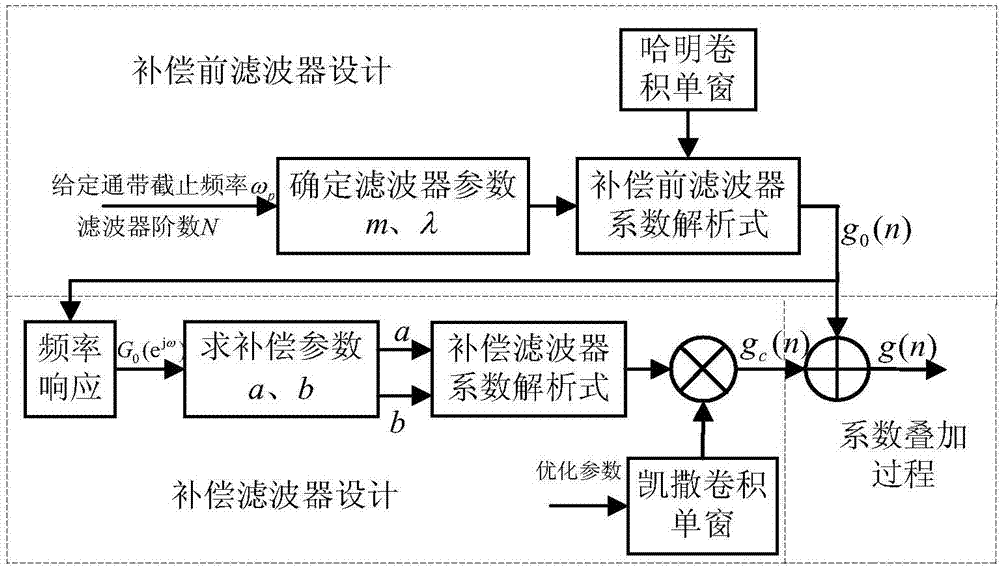
[0046] Aiming at the deficiencies of the document [10], the present invention deduces the analytical expression of the final filter that comprises boundary frequency band value, filter order N and convolution window Kaiser value on the one hand, according to this expression, just can draw boundary frequency band The filter coefficients can be precisely controlled, the passband ripple is small, and the stopband attenuation is large; on the other hand, it is proposed that the convolution window of the compensation filter can be directly obtained only according to the expected boundary frequency band value, translation amount and filter order N Kaiser value parameter rapid setting method, this setting method can ensure that the final filter has better transmission performance in the...


PUM


Abstract

The invention discloses a method and device for configuring the boundary frequency band of an efficient filter rapidly. The method for configuring the boundary frequency band of the efficient filter rapidly comprises the steps that relevant pass band parameters of the filter and the translation parameters are obtained according to the pass band cut-off frequency of the filter and the order of the filter, and the filter coefficient with the length being 2N-1 existing before compensation is obtained according to the relevant pass band parameters of the filter and the translation parameters; a filter coefficient is obtained according to the filter coefficient existing before compensation, the Kaiser window parameter and a compensating filter coefficient analytic expression; the filter coefficient existing before compensation and a compensating filter coefficient are added, so that the final filter coefficient is obtained. The device for configuring the boundary frequency band of the efficient filter rapidly comprises an external RAM, a DSP, an output driver and a display circuit. According to the method and device for configuring the boundary frequency band of the efficient filter rapidly, parameters required for compensating the filter are calculated according to the filter coefficient existing before compensation and a transmission curve and are fed back to be stored in the external RAM, and all the parameters required for designing the filter are input into the DSP through the external RAM, so that the required filter coefficient and the transmission curve are obtained and are displayed through the output driver and the display circuit.

Description

technical field [0001] The invention relates to the field of digital signal processing, in particular to a fast-configurable high-efficiency filter method and device for a boundary frequency band. Background technique [0002] The finite impulse response filter (Finite Impulse Response Filter, FIR Filter) design is the basis of the field of digital signal processing, in the spectrum analysis [1] ,Image Processing [2] , audio signal processing, codec and other digital signal fields play a vital role. In digital filtering, the control of the filter boundary frequency band (that is, the frequency band at the intersection of the passband and the stopband of the filter transmission curve) is a very critical technology, such as the Co-prime Sensing proposed by Palghat P.Vaidyanathan [3-6] The theory puts forward strict requirements on the control of the filter boundary frequency. If the boundary frequency band is not well controlled, spectral leakage will be introduced into the ...

Claims


Application Information

Patent Timeline
IPC IPC(8): H03H17/02
Inventor 黄翔东闫子阳冼弘宇吕卫
Owner TIANJIN UNIV
Why Eureka
Try Eureka