
Optical fiber communication network monitoring protecting system and method thereof

A technology for network monitoring and optical fiber communication, applied in the field of electrical communication, can solve the problems of lack of comprehensive and effective technical means for the evaluation and judgment of communication optical cable status, lack of automatic protection function of optical cable, inability to automatically solve optical cable faults, etc., so as to improve stability. reliability and reliability, reducing misjudgments, and reducing losses

Inactive Publication Date: 2015-01-14
李水进 +1
View PDF6 Cites 17 Cited by
  • Summary
  • Abstract
  • Description
  • Claims
  • Application Information

AI Technical Summary

Problems solved by technology

[0014] From the above analysis, it can be known that the existing optical fiber communication network monitoring and protection system lacks the automatic protection function for optical cables, and can only alarm and locate faults, but cannot automatically solve optical cable faults. Moreover, the evaluation and judgment of communication optical cable status lack comprehensive, Effective technical means, in short, the reliability and stability of the existing technology is not high; in addition, the existing optical fiber communication network monitoring and protection system uses a single wired network, which will be paralyzed when the wired network fails

Method used


Image

  • Optical fiber communication network monitoring protecting system and method thereof
  • Optical fiber communication network monitoring protecting system and method thereof
  • Optical fiber communication network monitoring protecting system and method thereof

Examples


Embodiment Construction

[0046] Below in conjunction with accompanying drawing and specific embodiment the present invention is described in further detail:

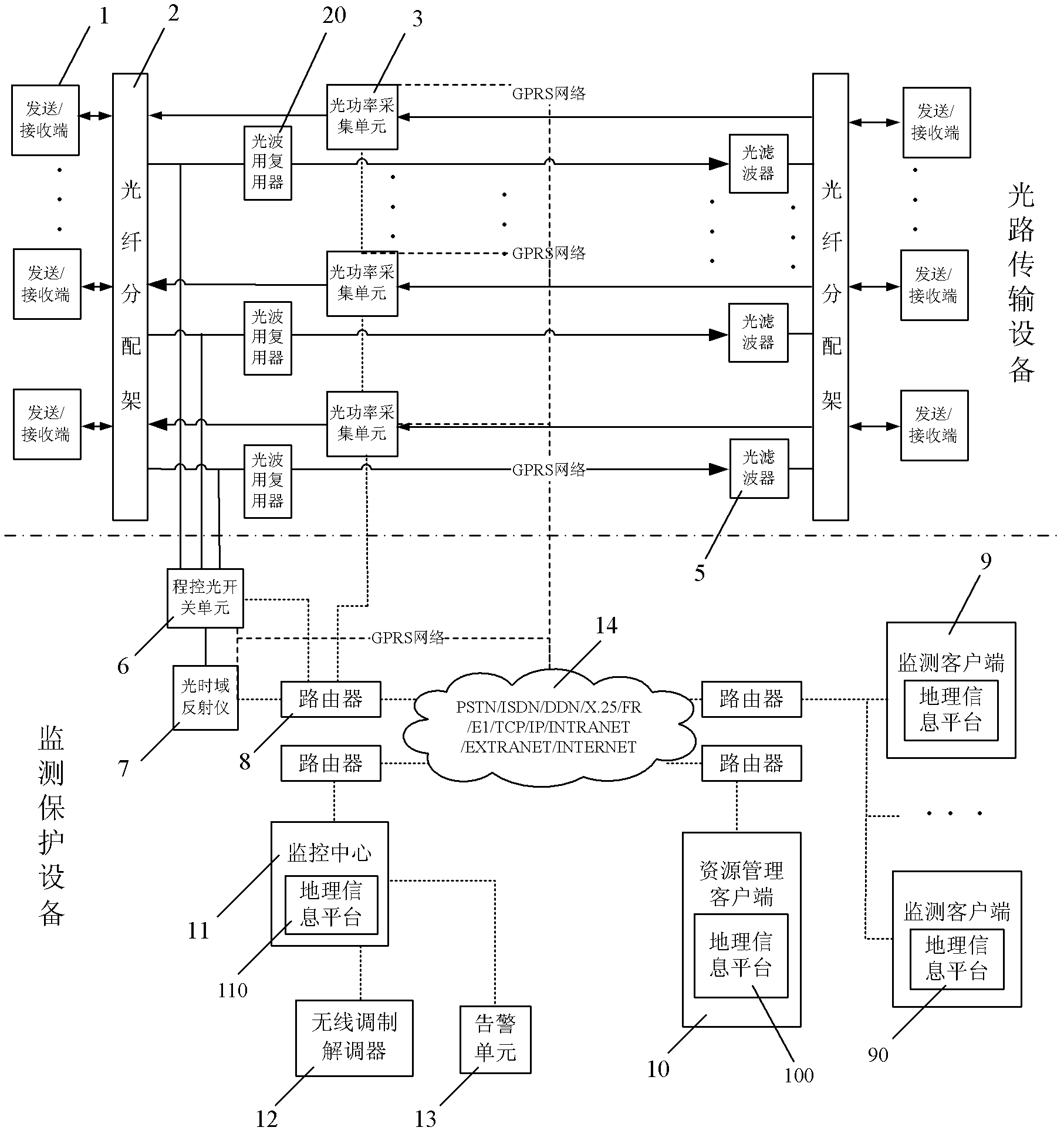
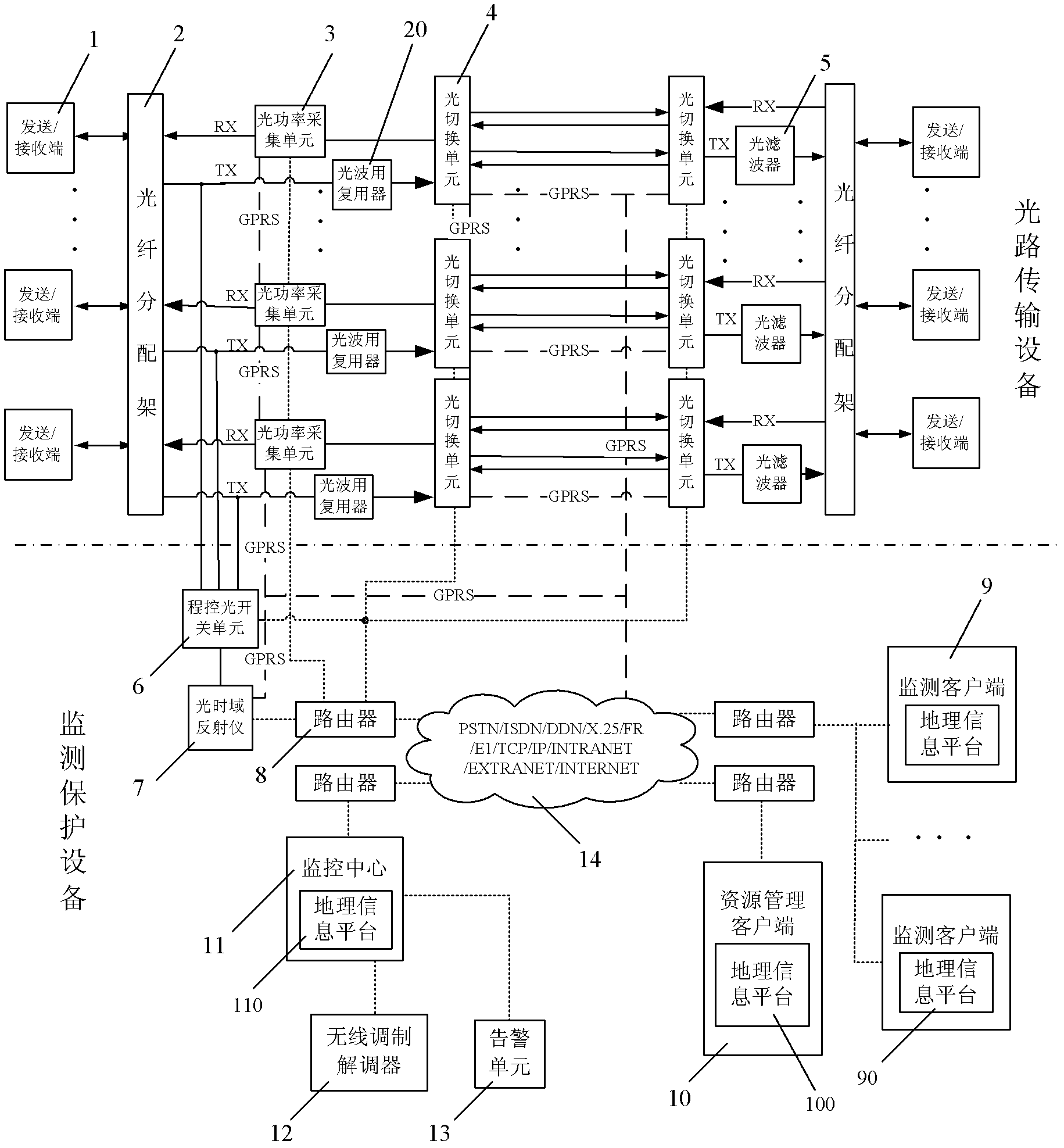
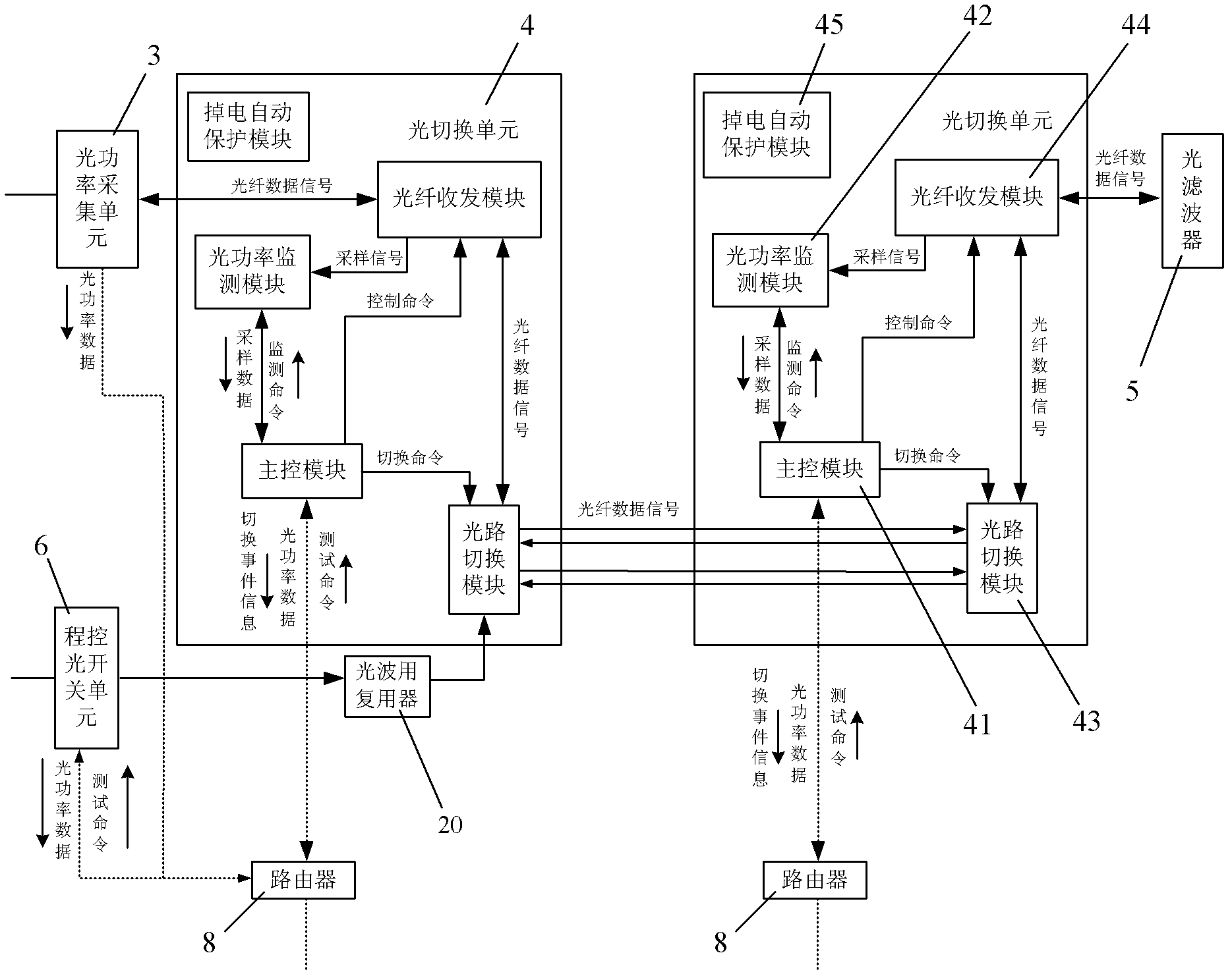
[0047] refer to figure 2 As shown, the present invention discloses a monitoring and protection system for an optical fiber communication network, which includes optical transmission equipment and monitoring and protection equipment, and the optical transmission equipment includes a pair of optical fiber distribution racks 2 (two optical fiber distribution racks) and at least one set of optical Transmission device, each group of optical transmission devices includes a sending / receiving end 1, an optical power acquisition unit 3, an optical filter 5 and a light wave multiplexer 20, and the sending / receiving end 1 is connected to the optical fiber distribution frame 2, that is, a There are two sending / receiving ends 1 in the group optical transmission device, which are respectively connected to two optical fiber distribution racks 2, the optical p...


PUM


Abstract

The invention discloses an optical fiber communication network monitoring protecting system and a method thereof. The optical fiber communication network monitoring protecting system comprises optical path transmission equipment and monitoring protecting equipment. The improvement of the optical fiber communication network monitoring protecting system is characterized in that the optical path transmission equipment comprises an optical switching unit; the optical switching unit monitors optical power data in real time, determines optical fault state and performs corresponding optical path switching; and a monitoring center receives monitoring data and information of an optical power acquiring unit and the optical switching unit and performs comprehensive analysis on the line state. The method comprises the steps of: A. performing real-time monitoring on the optical power by the optical power acquiring unit and the optical switching unit respectively, when a fault of the optical path occurs, finishing corresponding switching by the optical switching unit, and reporting the monitoring data and information to the monitoring center through a network; B. analyzing by the monitoring center for determining whether switching of the optical switching unit is correct, and then performing the following operations: B1, if switching is incorrect, transmitting an original state returning command by the monitoring center to the optical switching unit, and B2, if switching is correct, starting fault point testing for determining the geographical position of the fault point. The optical fiber communication network monitoring protecting system has high reliability and high stability.

Description

【Technical field】 [0001] The invention relates to electric communication technology, in particular to a method and system for monitoring and protecting an optical fiber communication network using GPRS wireless communication technology. 【Background technique】 [0002] In recent years, with the development of optical network equipment and technology, especially now that the world-wide optical fiber communication and optoelectronic industry has entered a new era, all-optical communication network technology and equipment based on advanced optical devices and optical signal processing technology have been obtained. Wider range of applications. [0003] At present, with the rapid development of optical cable applications, the maintenance and management of optical cables have become increasingly prominent. As the use time increases, the optical fiber itself will gradually deteriorate, resulting in failures and hidden dangers, and the number of failures of optical cable lines wil...

Claims


Application Information

Patent Timeline
Patent Type & Authority Applications(China)
IPC IPC(8): H04B10/032H04B10/077
Inventor 李水进丁继强
Owner 李水进
Learn More