Heat exchanger and air conditioner

A technology for heat exchangers and heat transfer tubes, applied to indirect heat exchangers, heat exchanger types, heat sinks, etc., can solve problems such as reduced frost resistance, increased air ventilation resistance, and air flow obstruction, achieving Improved rigidity, improved frost resistance, and improved heat exchange performance

Active Publication Date: 2015-01-14
MITSUBISHI ELECTRIC CORP
View PDF7 Cites 8 Cited by
  • Summary
  • Abstract
  • Description
  • Claims
  • Application Information

AI Technical Summary

Problems solved by technology

[0007] In addition, when the fin-and-tube heat exchanger is used in an environment where frost occurs, there is a problem that frost is likely to occur on the fins and heat transfer tubes on the windward side where the absolute humidity in the air is large. Frosting increases ventilation resistance, reduces air volume and reduces heat exchange performance
In particular, in the case of forming a slit-shaped portion formed by cutting a part of the fins, there is a problem that frost is likely to form on the slit portion with high heat transfer perfor

Method used


Image

  • Heat exchanger and air conditioner
  • Heat exchanger and air conditioner
  • Heat exchanger and air conditioner

Examples


Embodiment approach 1

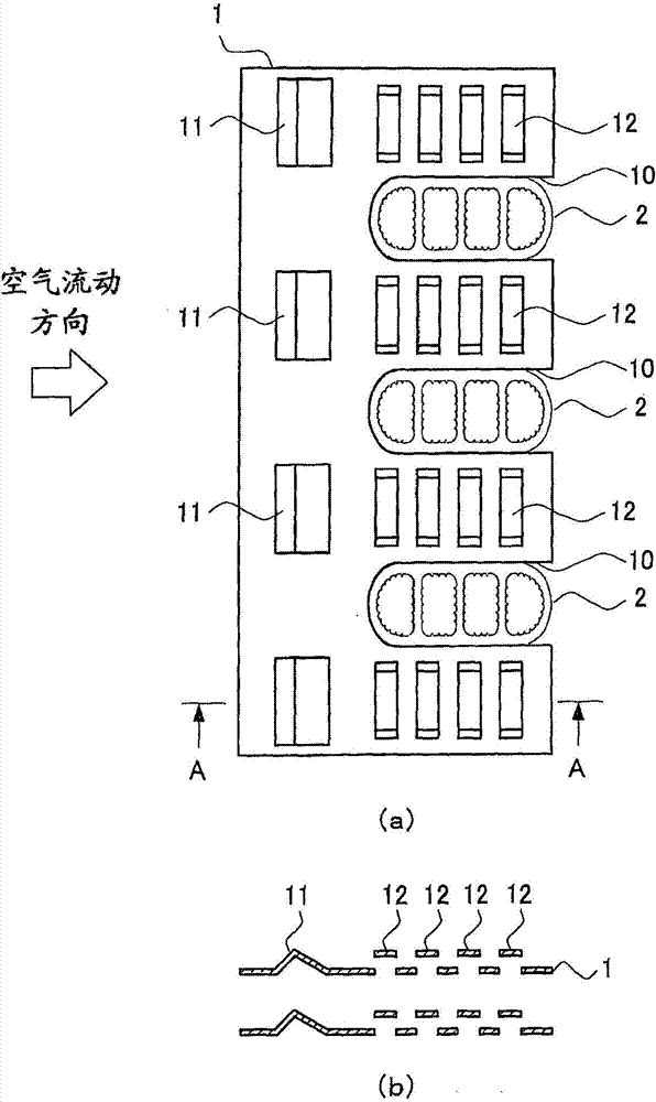
[0029] figure 1 It is a block diagram of the heat exchanger in Embodiment 1 of this invention. figure 1 (a) is a figure which shows the arrangement|positioning relationship of a plate-shaped fin and a heat transfer tube, figure 1 (b) means that figure 1 (a) A-A section diagram. In addition, in figure 1 In , the key parts of the heat exchanger are schematically represented.

[0030] Such as figure 1 As shown, the fin-tube heat exchanger according to Embodiment 1 has plate-shaped fins 1 and flat tubes 2 as heat transfer tubes. This heat exchanger is mounted on, for example, an air conditioner, and exchanges heat between a fluid (hereinafter also referred to as air flow) such as air passing through the heat exchanger and a refrigerant (medium) flowing through the flat tubes 2 .

[0031] The flat tube 2 is a heat transfer tube whose cross-sectional shape is flat or wedge-shaped. The long axis of the flat tube 2 is oriented toward the flow direction of the fluid (left-right ...

Embodiment approach 2

[0069] Figure 7 It is a configuration diagram of a heat exchanger according to Embodiment 2 of the present invention. Figure 7 (a) represents the configuration relationship between plate fins and heat transfer tubes, Figure 7 (b) means Figure 7 (a) A-A section. In addition, in Figure 7 In , the key parts of the heat exchanger are schematically represented.

[0070] like Figure 7 As shown, in Embodiment 2, notches 10 for inserting the plurality of flat tubes 2 are formed at the upstream end of the plate fin 1 . In addition, the airflow downstream side of the cutout 10 portion of the plate-shaped fin 1 is a flat flat portion.

[0071] In Embodiment 2, the waffle-shaped portion 11 and the slit-shaped portion 12 are also formed on the plate-shaped fin 1 .

[0072] The waffle-shaped portion 11 is provided on the upstream side of the air flow from the slit-shaped portion 12 . In addition, the waffle-shaped portion 11 is disposed on the upstream side of the upstream end...

Embodiment approach 3

[0084] Figure 9 It is a configuration diagram of a heat exchanger according to Embodiment 3 of the present invention. Figure 9(a) represents the configuration relationship between plate fins and heat transfer tubes, Figure 9 (b) means Figure 9 (a) A-A section. In addition, in Figure 9 In , the key parts of the heat exchanger are schematically represented.

[0085] Such as Figure 9 As shown, in Embodiment 3, a plurality of slit-shaped portions 12 are formed on the plate fin 1 , and the opening width of the slit-shaped portion 12 on the downstream side is formed wider than that of the opening of the slit-shaped portion 12 on the upstream side. Wide. That is, the opening width W of the slit is formed to be larger as it goes from the upstream side to the downstream side.

[0086] The other configurations are the same as those in Embodiment 1 or 2 above, and the same reference numerals are assigned to the same parts. In addition, in Figure 9 In the example shown, al...


PUM


Abstract

Provided is a heat exchanger in which: condensed water drainability can be improved; resistance to frosting can be improved; heat exchange performance can be improved; and fin rigidity can be improved. Also provided is an air conditioner using said heat exchanger. A plate-shaped fin (1) comprises: a slit shape (12) that is formed by cutting and raising a portion of the plate-shaped fin (1) and that is opened so as to oppose the flow of a fluid; and a waffle shape (11) formed into a mountain shape, in cross section, that protrudes in the stacking direction by bending a portion of the plate-shaped fin (1), the ridge line of the mountain shape being substantially orthogonal to the air flow direction. The waffle shape (11) is provided more on the upstream side of the fluid than the slit shape (12), and is made such that the slope length (L1) of the mountain shape on the upstream side is shorter than the slope length (L2) on the downstream side.

Description

technical field [0001] The present invention relates to a heat exchanger and an air conditioner using the heat exchanger. Background technique [0002] In conventional heat exchangers, for the purpose of achieving both the improvement of drainage of condensed water and the improvement of heat transfer performance of the fins, it has been proposed that "a tube with a flat cross section extending in the vertical direction ( 2) In the middle of the air flow direction (A), a drainage groove (10) for guiding the condensed water downward is formed, and it is joined to the outer surface of the pipe (2). In the fin (5), a gap (53) is formed at a portion facing the drain groove (10), and the corrugated fin (5) is partitioned into the windward side of the air flow direction (A) by the gap (53). The first fin (51) on the leeward side and the second fin (52) on the leeward side" (for example, refer to Patent Document 1). [0003] prior art literature [0004] patent documents [000...

Claims


Application Information

Patent Timeline
IPC IPC(8): F28F1/32
CPCF28F2215/10F28F1/325F28F17/005F28F2215/12F28D1/0535F28F1/128F28F1/40F28F1/022F25B1/005F28D9/0062
Inventor 李相武松田拓也石桥晃冈崎多佳志
Owner MITSUBISHI ELECTRIC CORP
Why Eureka
Try Eureka