Corn kernel threshing and separating device

A technology for threshing and separating grains, applied in threshing equipment, applications, agricultural machinery and tools, etc., can solve the problems of unfavorable large-scale production, poor strength of threshing concave plates, high production and use costs, etc., to achieve enhanced threshing effect and ability, increase The effect of working time and low cost of use

Active Publication Date: 2015-01-21
LOVOL HEAVY IND CO LTD
View PDF5 Cites 11 Cited by
  • Summary
  • Abstract
  • Description
  • Claims
  • Application Information

AI Technical Summary

Problems solved by technology

At the present stage, there are two main methods of corn machine harvesting in my country: one is to use an ear picking and peeling machine to pick off the ears and peel off the bract leaves. After the ears are dried in the sun, they are threshed by a corn thresher. There are many links, and the loss of grain is large, which increases the cost and is not conducive to large-scale production; one is to use the corn combine harvester to directly harvest the corn grain by replacing the corn accessories such as the threshing mechanism. This method is efficient and improves the harvester. Therefore, direct harvesting of corn kernels is increasingly becoming a trend for machine harvesting of corn
[0005] However, the current threshing and separation device used for harvesting corn kernels crushes the ears of corn and threshes the kernels through the extrusion method of the threshing roller and the threshing concave plate. Larger, higher production and use costs. At the same time, the strength of the threshing concave plate is poor, easy to deform and damage, resulting in high maintenance costs

Method used


Image

  • Corn kernel threshing and separating device
  • Corn kernel threshing and separating device
  • Corn kernel threshing and separating device

Examples


Embodiment Construction

[0034] In order to make the object, technical solution and advantages of the present invention clearer, the present invention will be further described in detail below in conjunction with the accompanying drawings and embodiments. It should be understood that the specific embodiments described here are only used to explain the present invention, not to limit the present invention.

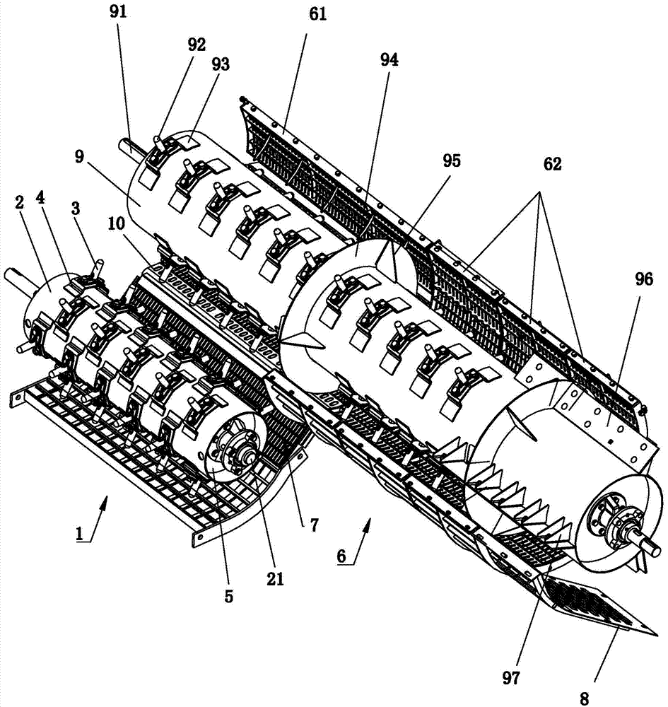
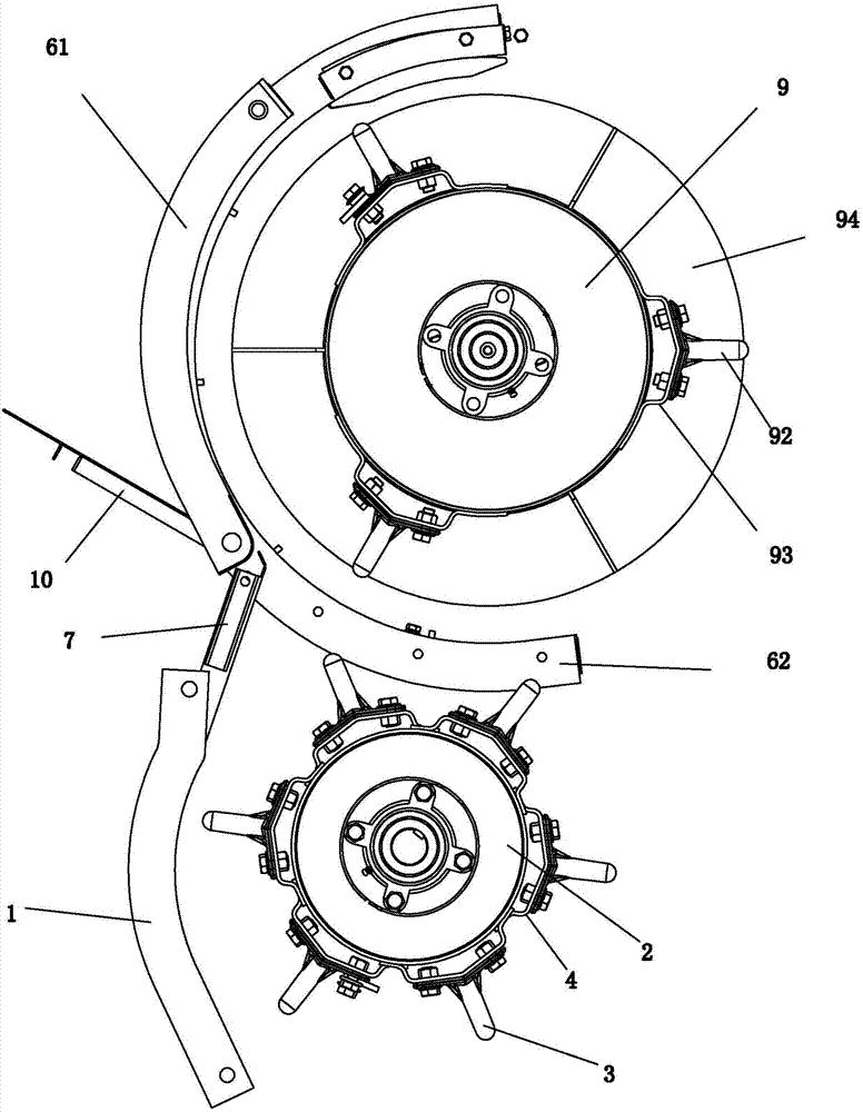
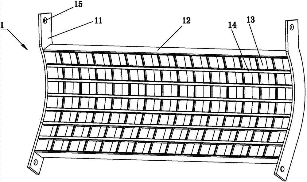
[0035] like Figure 1 to Figure 6Commonly shown, the corn grain threshing separation device includes a threshing cylinder 2 arranged on the rice and wheat harvester, and the threshing cylinder 2 is provided with a number of threshing teeth 3, and the threshing teeth 3 include a cylindrical tooth bar 301, the tooth bar The top of 301 is cylindrical with a spherical head, and the bottom of the gear bar 301 is provided with a herringbone base 303, the bottom of the gear bar 301 is located at the highest point of the herringbone base 303, and the two ends of the herringbone base 303 are respectively pr...


PUM


Abstract

The invention discloses a corn kernel threshing and separating device which comprises a threshing roller with threshing teeth. Each threshing tooth comprises a tooth rod with a spherical top end, a threshing concave plate is arranged below the threshing roller and comprises a concave plate body, the concave plate body comprises two side plates, supporting plates are arranged between the two side plates, a longitudinal separation plate is arranged between the two supporting plates, separation bars are arranged on the longitudinal separation plate, and the separation bars and the longitudinal separation plate are flush with the side plates. A separation roller is arranged on one side of the flowing direction of crops, and separation teeth and separation plates are arranged on the separation roller in a staggered mode. A separation concave plate communicated with the threshing concave plate is arranged below the separation plate. Through rubbing between the threshing teeth and the threshing concave plate, threshing is achieved, power consumption is little, and cost is low. Through the threshing concave plate, while passing ability and screening efficiency are guaranteed, strength and use reliability are improved, and the crushing rate is lowered; meanwhile, through replacement of the corn kernel threshing and separating device, the effect of harvesting corn crops at the same time is achieved, and the use rate of a rice and wheat harvester is improved.

Description

technical field [0001] The invention belongs to the technical field of corn threshing, and in particular relates to a combine harvester of a corn grain threshing and separation device. Background technique [0002] At present, my country's food crops are diverse, widely distributed, and have large regional differences. Among them, wheat, rice, and corn are the most widely distributed and produce the most, and the three together account for more than 86% of the country's total grain output. The corresponding combine harvesters are also divided into wheat combine harvesters, rice combine harvesters, corn combine harvesters, etc. Under the influence of the trend of international harvest machinery technology progress and the promotion of new requirements for accelerating the development of modern agriculture, my country's harvest machinery product technology began to change from Small and medium-sized, single-function to multi-variety, multi-functional development. [0003] In ...

Claims


Application Information

Patent Timeline
Patent Type & Authority Applications(China)
IPC IPC(8): A01F12/44A01F11/06
Inventor 王乐刚焦中元朱现学朱永丰李建香宋理成沈永泉
Owner LOVOL HEAVY IND CO LTD
Why Eureka
Try Eureka