Mixed-material discharging apparatus capable of realizing uniform mixing of materials

A technology of uniform mixing and discharging device, applied in mixers, mixers with rotary stirring devices, dissolving and other directions, can solve the problems affecting mixing quality and uneven mixing, etc., to improve mixing quality, reduce friction, reduce effect of load

Inactive Publication Date: 2015-01-21
成都远峰科技发展有限公司
View PDF0 Cites 23 Cited by
  • Summary
  • Abstract
  • Description
  • Claims
  • Application Information

AI Technical Summary

Problems solved by technology

[0003] The problem to be solved by the present invention is to provide a uniformly mixed mixing and discharging device, which can improve the mixing degree of mixed raw materials and improve the mixing quality, and solve the problem of uneven mixing and affecting the mixing quality of the previous devices when mixing raw materials

Method used


Image

  • Mixed-material discharging apparatus capable of realizing uniform mixing of materials

Examples


Embodiment

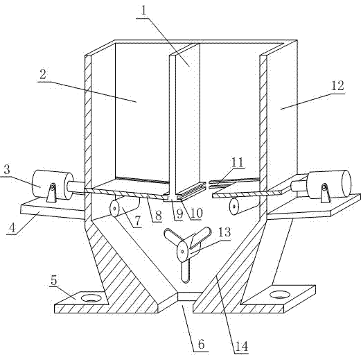
[0014] Such as figure 1 Shown: a uniform mixing and discharging device, including a metal shell 12, the metal shell 12 is provided with a discharge cavity 2, and the middle part of the discharge cavity 2 is vertically provided with a partition separating the discharge cavity 2 The partition 1, the metal shell 12 is located in the discharge cavity 2, and the left and right sides of the lower end of the partition 1 are respectively inclined to be provided with baffles 8, and the two baffles 8 pass through the left and right sides respectively. The metal shells 12 on the right sides are connected with hydraulic cylinders 3, and the hydraulic cylinders 3 can drive the baffles 8 to move. The hydraulic cylinders 3 are fixed by the fixing plates 4 at the outer ends of the metal shells 12. The lower end of the lower end is also provided with a driven roller 7 which is in contact with the baffle plate 8. The metal shell 12 is provided with a material leakage port 6 in the middle of the...

Embodiment 2

[0020] In this embodiment, the following structure is added on the basis of Embodiment 1, specifically: a guide chute 11 is provided inside the metal shell 12 , and the side ends of the two baffles 8 are located inside the guide chute 11 .

[0021] The guide chute 11 of this embodiment is used to limit and guide the baffle 8 to move in a certain direction, which not only plays a supporting role for the baffle 8, reduces the vibration that occurs when it moves, but also ensures the movement of the baffle 8 The direction reduces the friction between it and the metal shell 12, reduces the friction noise, and also makes the baffle 8 move more smoothly.

Embodiment 3

[0023] This embodiment is further limited on the basis of embodiment 1 or embodiment 2, specifically: the range of inclination angle of the aggregate slope 14 is 70°-90°.

[0024] In order to make the collection slope 14 have a good guiding and buffering effect in this embodiment, its inclination angle is limited between 70°-90°, so that the collection slope 14 can not only guide the raw materials to leak from the leakage port 6, but also prevent The accumulation of raw materials on the aggregate slope 14 affects the discharge, and at the same time, the raw materials can slowly fall to the leakage port 6 on the collection slope 14 with the action of gravity, so as to prevent the raw materials from blocking the leakage port 6 at one time, and play a good role. buffering effect.


PUM


Abstract

A disclosed mixed-material discharging apparatus capable of realizing uniform mixing of materials comprises a metal housing; the metal housing is inside provided with a discharging cavity, and the center of the discharging cavity is vertically provided with a separation plate dividing the discharging cavity; in the discharging cavity, the metal housing is provided with obliquely-arranged baffle plates respectively at the left side and the right side of the lower end of the separation plate; the two baffle plates both penetrate the metal housing respectively at the right part and the left part and are both connected with a hydraulic cylinder; each hydraulic cylinder is capable of driving the corresponding baffle plate to move, and is fixed via a corresponding fixing plate at the corresponding outer end of the metal housing; the lower end of each baffle plate is provided with a driven roll wheel contacted with the baffle plate; at the center of the lower end of the discharging cavity, the metal housing is provided with a material leakage port; the interior, at the upper end of the material leakage port, of the metal housing is provided with an electric stirring paddle; and the inner lateral sides, at two ends of the material leakage port, of the metal housing are material-integrating inclined planes. The mixed-material discharging apparatus does not contain residual raw materials in the discharging cavity, deformation and vibration of the baffle plates are reduced, and the apparatus is capable of fully mixing the raw materials and improving the mixing quality.

Description

technical field [0001] The invention relates to a discharging device, in particular to a uniformly mixing and discharging device, which belongs to the field of industrial machinery. Background technique [0002] In some raw material processing and mixture processing, discharge devices such as discharge boxes and discharge valves for discharge are often used. Most of these discharge devices have complex structures and are inconvenient to use, and many of them can only be used for one For the discharging of raw materials, when two mixtures of raw materials need to be placed, the device itself cannot mix well, and it can only be discharged after fully mixing through the mixing device. It cannot be "one machine for multiple purposes", and its practicability is poor. Although the current feeding device can realize the mixing of raw materials, it is difficult to mix the two raw materials evenly. For some mixtures that require a high degree of mixing, the device is difficult to mee...

Claims


Application Information

Patent Timeline
Patent Type & Authority Applications(China)
IPC IPC(8): B01F7/04B01F15/02
Inventor 陈安民
Owner 成都远峰科技发展有限公司
Why Eureka
Try Eureka