Processing method of ring screw hole on mold

A processing method, the technology of lifting ring screw, which is applied in the processing field of the screw hole of the lifting ring on the mold, can solve the problems such as the main shaft swings violently, the lifting ring is broken, and cannot meet the needs of customers, so as to shorten the processing cycle, improve the force strength, reduce the The effect of rework rate

Active Publication Date: 2016-11-09
宁波富信模胚有限公司
View PDF6 Cites 0 Cited by
  • Summary
  • Abstract
  • Description
  • Claims
  • Application Information

AI Technical Summary

Problems solved by technology

The traditional processing methods have gradually been unable to meet the needs of customers
[0004] The traditional processing method of screw holes for lifting rings is described as follows: using a radial drilling machine, first use a twist drill to drill the threaded bottom hole, and then use a tap to tap (that is, process internal threads); the disadvantages of this processing method are: the power of the spindle of the radial drill It is not big enough and the precision is not high enough. During the processing, the main shaft swings violently and jumps seriously, and the verticality of the threaded bottom hole cannot be guaranteed. The threaded bottom hole is often prone to inclination, ellipse, and roughness. The upper twist drill will be worn during processing, and the cylindrical hole of the threaded bottom hole is often made into a tapered hole, that is, the diameter of the outer end of the threaded bottom hole is larger than the diameter of the inner end, especially the threaded bottom hole drilled by twist drill The inner section is a triangle, such as figure 2 As shown, after tapping, the lifting eye screw cannot be fully screwed to the bottom of the tooth hole, so that the end face of the end face of the lifting ring screw and the end face of the outer port of the lifting ring screw hole cannot be tightly fitted, and the rework rate of the workpiece is high; in addition, during the lifting process, Only the screw part of the lifting ring bears the force. According to the principle of leverage, the screw part of the lifting ring bears a large force, which can easily cause the lifting ring to be pulled off, posing a safety hazard

Method used


Image

  • Processing method of ring screw hole on mold
  • Processing method of ring screw hole on mold
  • Processing method of ring screw hole on mold

Examples


Embodiment Construction

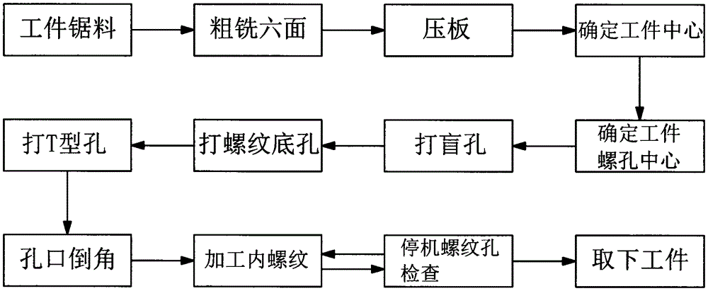
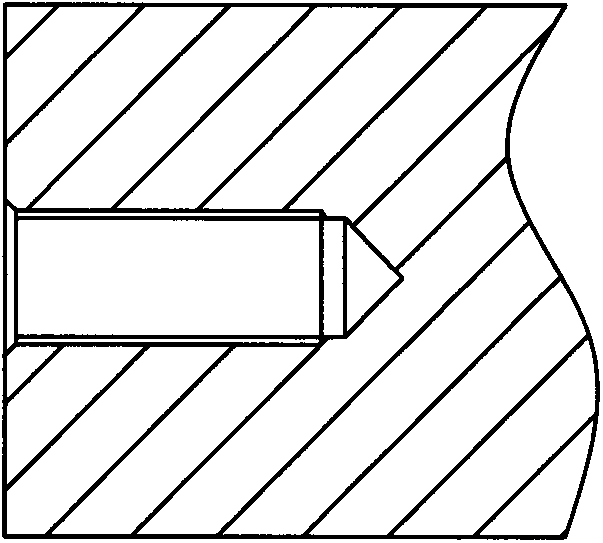
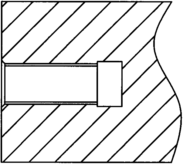
[0026] refer to figure 1 , figure 2 and image 3 Shown, the present invention a kind of processing method of ring screw hole on the mould, the technological process of this method is successively, workpiece sawing, rough milling six sides, pressing plate, determine workpiece center, determine workpiece screw hole center, punch blind hole, punch Threaded bottom hole, T-shaped hole punching, hole chamfering, internal thread processing, stop threaded hole inspection, and removal of the workpiece; The sawing machine intercepts the rectangular material steel plate used to make the mold from the large steel plate of the raw material; the drawing is an exploded view of the engineering details of the mold product;

[0027] The rough milling of the six sides is based on the size of the drawing and the machining allowance of the subsequent process is reserved, and the oxide layer on the six surfaces of the material steel plate is milled off with a milling machine to obtain a smooth p...


PUM


Abstract

The invention discloses a method for machining a hoisting ring threaded hole in a die, and belongs to the technical field of threaded hole machining technologies. The technological process of the method sequentially comprises the steps of sawing workpiece materials from a steel plate, carrying out rough milling on six faces, pressing the steel plate, determining the center of a workpiece, determining the threaded hole center of the workpiece, drilling a blind hole, drilling a threaded bottom hole, drilling a T-shaped hole, carrying out orifice chamfering, machining internal threads, halting to carry out threaded hole check and taking off the workpiece. According to the method, a cylindrical cavity with the inner diameter larger than that of the threaded bottom hole by 0.4-1mm is milled out in the bottom of the threaded bottom hole through a T-shaped grooving cutter through the adoption of a machining center. The hoisting ring threaded hole is shaped like a T, and compared with a cone at the bottom of the hoisting ring threaded hole in the prior art, the radial dimension of the inner end of the hoisting ring threaded hole manufactured through the method becomes large. The method has the advantages that the rework rate is reduced, production is quicker and more convenient, quality is more stable, machining is simpler, safety is higher and adaptability is wider.

Description

technical field [0001] The invention relates to the technical field of screw hole processing technology, in particular to a method for processing screw holes of suspension rings on a mold. Background technique [0002] In recent years, with the rapid development of the plastics industry and the continuous improvement of the strength and precision of general and engineering plastics, the application range of plastic products is also expanding, such as: household appliances, instruments, construction equipment, automobile industry, Japan In many fields such as hardware, the proportion of plastic products is increasing rapidly. A properly designed plastic part can often replace multiple traditional metal parts. The trend of plasticization of industrial products and daily products is on the rise. The production of these plastic products is inseparable from the mold. The mold is a tool for the production of plastic products. It is composed of some basic plates and parts such as...

Claims


Application Information

Patent Timeline
Patent Type & Authority Patents(China)
IPC IPC(8): B23P15/24
CPCB23P15/24
Inventor 丁全福陈鹏陈胜李依娜黄建萍
Owner 宁波富信模胚有限公司
Why Eureka
Try Eureka