Multipurpose mechanical gripper

A mechanical claw and multi-purpose technology, applied in the direction of load hanging components, transportation and packaging, etc., can solve the problems of poor working stability and reliability, uncoordinated work of the double oil cylinder structure, large force on the two claws, etc., and achieve improved Stability and reliability, manufacturing cost savings, and strength enhancement effects

Inactive Publication Date: 2015-01-21
黄全
View PDF6 Cites 1 Cited by
  • Summary
  • Abstract
  • Description
  • Claims
  • Application Information

AI Technical Summary

Problems solved by technology

This kind of log grab has the following disadvantages: ①The log grab is dedicated to the machine, and the operating cost is high; ②Double oil cylinder design, one oil cylinder is connected to the boom and the support device for lifting, and the other oil cylinder is located between the two claws. For the grasping and clamping of wood, the structure is more complicated, the control is more cumbersome, and the maintenance and maintenance are large; ③As the tonnage gradually increases, the distance between the two claws is also increasing. The way of opening and closing the claws makes the work efficiency low when grasping small wood, and it is easy to spread materials, and the work adaptability is poor; ④The structure of the double oil cylinder is not coordinated, and the force between the two claws is large and easily damaged, resulting in stable work Poor performance and reliability

Method used


Image

  • Multipurpose mechanical gripper
  • Multipurpose mechanical gripper
  • Multipurpose mechanical gripper

Examples


Embodiment Construction

[0013] The present invention will be further described below with reference to the drawings and specific implementations of the specification. The following front and rear are only for convenience of description. The side of the cylinder rod of the excavator is defined as the front, and the side of the support mechanism of the excavator is defined as the rear. The front and rear settings of the excavator are generally recognized in the industry.

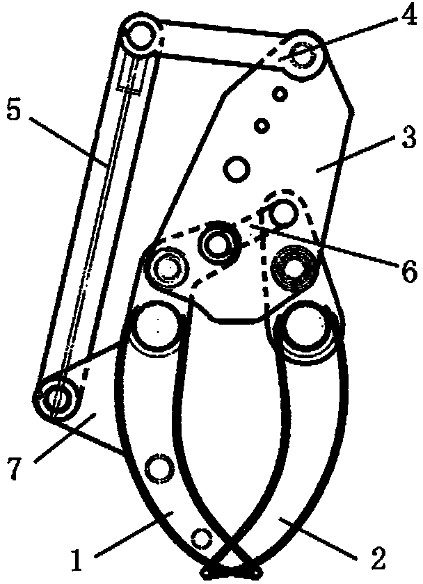
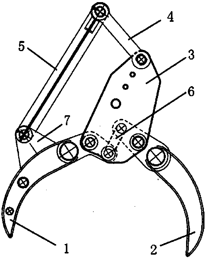
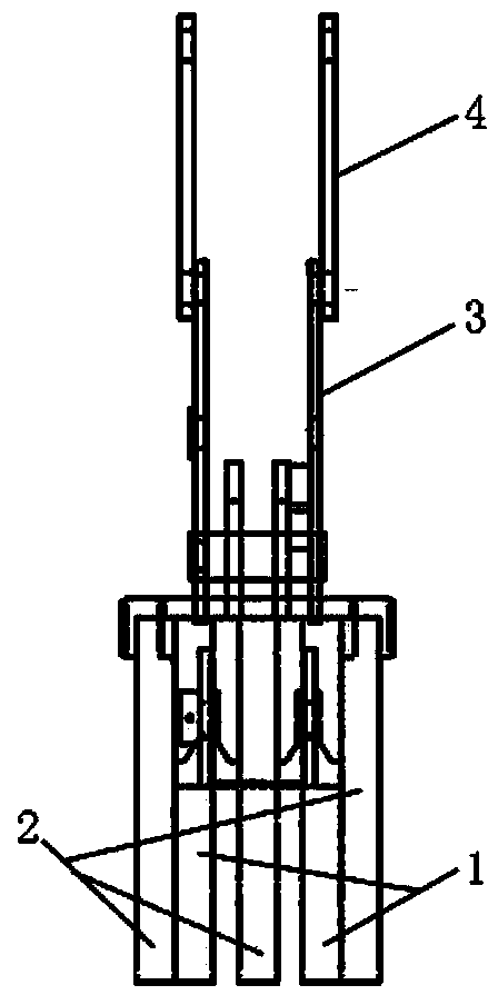
[0014] Such as figure 1 , 2 As shown in Figure 3, a multi-purpose mechanical claw mainly includes a front jaw 1, a rear jaw 2 and a connecting structure. The front jaw 1 and the rear jaw 2 can be opened and closed to claw objects. The opening and closing of the two jaws is completed by the hydraulic or vapor pressure transmission mechanism on the mechanical arm. Such as image 3 As shown, in this embodiment, the front jaw 1 has 2 clamping teeth, the rear jaw 2 has 3 clamping teeth, and the front clamping teeth and the rear clamping te...


PUM


Abstract

A multipurpose mechanical gripper is mainly composed of a front jaw, a back jaw, a connecting plate and a connecting rod. The connecting rod comprises a front connecting rod and a back connecting rod; the upper end of the connecting plate is provided with a pin hole structure which can be connected with a mechanical arm; the front part of the lower end of the connecting plate is connected with a rotating shaft on the upper part of the front jaw; the back part of the lower end of the connecting plate is connected with a rotating shaft on the lower part of the back jaw; the two ends of the back connecting rod are connected with the rotating shaft on the upper end of the front jaw and the rotating shaft on the upper end of the back jaw, respectively; a connecting end is fixedly connected to the outer side face of the front jaw; the connecting end is connected with a rotating shaft on the lower end of the front connecting rod; the other end of the front connecting rod is provided with a pin hole structure which can be connected with a rotating shaft of an oil cylinder pull rod of the mechanical arm. The multipurpose mechanical gripper can be mounted on a vapor-pressure or hydraulic mechanical arm, the mechanical arm stretches and retracts to any place to grip rod materials in different sizes, the multipurpose mechanical gripper is convenient to disassemble and replace and is a multipurpose standby gripper for the mechanical arm.

Description

technical field [0001] The invention relates to the technical field of tools for loading and unloading rods, in particular to a special wood clamp suitable for supporting and using on an excavator. Background technique [0002] The relevant lifting equipment used in the wood loading and unloading and grabbing operations in the cargo yard and logging area is mostly equipped with door crane grabs, but the wood in the port wood ship loading and unloading is mainly 3 to 6 meters in size, and the wood in the pole and waist It is not within the working range of the door crane grab, and only manual work can be used, that is, after manually lifting one end of the log, use steel wire rope and other binding ropes to bind the wood, and then use a crane or other lifting equipment Lift the log, move it to a suitable position, lower it, and put it down. Unloading the wood also requires manually loosening the wire rope or rope. During the entire lifting process, multiple people cooperate t...

Claims


Application Information

Patent Timeline
Patent Type & Authority Applications(China)
IPC IPC(8): B66C3/04
CPCB66C1/427
Inventor 黄全
Owner 黄全
Why Eureka
Try Eureka