Sputtering device

A sputtering device and downstream technology, applied in sputtering plating, ion implantation plating, coating, etc., can solve problems such as deformation of long film substrates, surface panels that cannot be touched, poor appearance, etc.

Active Publication Date: 2015-01-21
NITTO DENKO CORP
View PDF5 Cites 1 Cited by
  • Summary
  • Abstract
  • Description
  • Claims
  • Application Information

AI Technical Summary

Problems solved by technology

[0005] As a result, there may be a problem that the elongated film substrate that is conveyed to the downstream side conveying roller and cooled rapidly is deformed, and cannot be used as a surface panel of a touch panel, etc., or has a poor appearance.
Especially, when the width of the elongated film substrate is large or the coefficient of linear expansion of the elongated film substrate is large, such problems remarkably occur.

Method used


Image

  • Sputtering device
  • Sputtering device
  • Sputtering device

Examples


Embodiment Construction

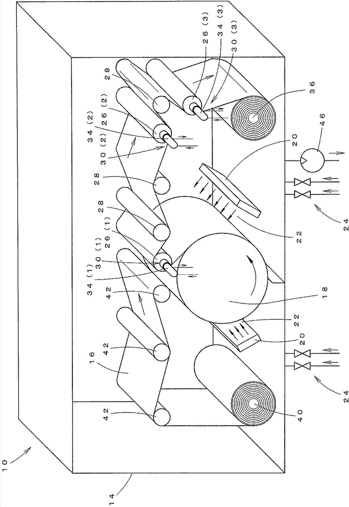
[0027] Next, embodiments of the present invention will be described in detail with reference to the drawings. exist figure 1 Among them, reference numeral 10 is the sputtering device of the present invention.

[0028] The sputtering device 10 is a device for forming a thin film on the surface of the elongated film substrate 16 conveyed along the surface of the film-forming roller 18, and the sputtering device 10 includes: a vacuum chamber 14; the above-mentioned film-forming roller 18, which Arranged in the vacuum chamber 14 in a rotatable manner; the target material 20, which is arranged in the vacuum chamber 14, is used to form a film-forming material on the surface of the elongated film substrate 16 conveyed along the surface of the film-forming roller 18 Gas supply mechanism 24, which is used to supply gas to the film-forming space 22 between the film-forming roller 18 and the target material 20; 3 driving rollers (downstream side conveying rollers) 26 (1), 26 (2), 26 ( ...


PUM


Abstract

A sputtering device includes a vacuum chamber; a film depositing roll; at least one target material; a gas supply mechanism; three drive rolls (downstream conveying rolls); and three temperature control mechanisms for maintaining a temperatures of the drive rolls substantially constant in a range where the temperature is 80° C. or less and is higher than a minimum temperature in the vacuum chamber so that a long film substrate that is detached from the film depositing roll and is conveyed to the downstream conveying rolls is not deformed by rapid cooling.

Description

technical field [0001] The present invention relates to a sputtering device for forming a thin film on the surface of a long film substrate conveyed along the surface of a film forming roller. Background technique [0002] Conventionally, a sputtering device is used in which the following components are arranged in a vacuum chamber: a raw material roll, which is wound with a long film substrate; a film forming roller, which makes the long film substrate along its surface; The film-forming material is formed on the surface of the long film substrate transported along the surface of the film-forming roller; the gas supply mechanism is used to supply gas to the film-forming space between the film-forming roller and the target material; the downstream side conveys Roller, which is used to convey the long film base material conveyed along the surface of the film forming roller to the downstream side of the conveying direction; Strip film substrate coiling (for example, referring...

Claims


Application Information

Patent Timeline
Patent Type & Authority Applications(China)
IPC IPC(8): C23C14/34
CPCH01J2237/332H01J37/32733C23C14/34H01J37/32715H01J37/32724H01J37/3277H01J37/34C23C14/3464C23C14/54C23C14/562
Inventor 梨木智刚滨田明
Owner NITTO DENKO CORP
Why Eureka
Try Eureka