Engine cooling water jacket

A technology for cooling water jackets and engines, applied in engine components, machines/engines, mechanical equipment, etc., can solve problems such as increased friction of piston components, deformation of the bottom surface of cylinder head, poor cooling effect of cylinder liner, etc., to increase the flow distance, extend the Service life, effect of improving emission levels

Inactive Publication Date: 2015-01-21
GUANGXI YUCHAI MASCH CO LTD
View PDF6 Cites 8 Cited by
  • Summary
  • Abstract
  • Description
  • Claims
  • Application Information

AI Technical Summary

Problems solved by technology

[0003] The existing technology mainly has the following problems: 1. The height H and thickness T of the water jacket of the cylinder block are relatively large, resulting in a large volume of the water jacket of the cylinder block, thereby reducing the flow rate of the coolant in the water jacket of the cylinder block and directly affecting the cylinder head. Coolant flow rate in water jacket
2. The water inlet of the cylinder block is set at the front end of the cylinder block, and the water outlet is set at the front end of the cylinder head. At the same time, the water holes of the water jacket of the cylinder block and the cylinder head are usually large casting water holes, and the size of the through hole set by the cylinder head gasket is basically the same. It is equivalent to the casting water hole of the cylinder block and cylinder head. Because the coolant flows into the cylinder head water jacket for each cylinder of the cylinder block water jacket, there is a short circuit effect, so there is a large amount of coolant from the water hole at the front end to the cylinder head, and the upper water hole at the rear end. The amount of water in the water hole is very small, resulting in uneven cooling of the front and rear ends of the cylinder block and cylinder head
[0004] The above two shortcomings will lead to poor cooling effect of the cylinder liner at the rear end of the cylinder block, increase the friction of the piston assembly, increase the fuel consumption of the engine, or even cause a cylinder failure when it is serious; at the same time, the cylinder head cannot get a good cooling effect (especially is the rear end), the deformation of the bottom surface of the cylinder head is large, which may cause reliability failures such as cylinder head gasket flushing and cylinder head cracking

Method used


Image

  • Engine cooling water jacket
  • Engine cooling water jacket
  • Engine cooling water jacket

Examples


Embodiment Construction

[0021] The specific embodiments of the present invention will be described in detail below in conjunction with the accompanying drawings, but it should be understood that the protection scope of the present invention is not limited by the specific embodiments.

[0022] Unless expressly stated otherwise, throughout the specification and claims, the term "comprise" or variations thereof such as "includes" or "includes" and the like will be understood to include the stated elements or constituents, and not Other elements or other components are not excluded.

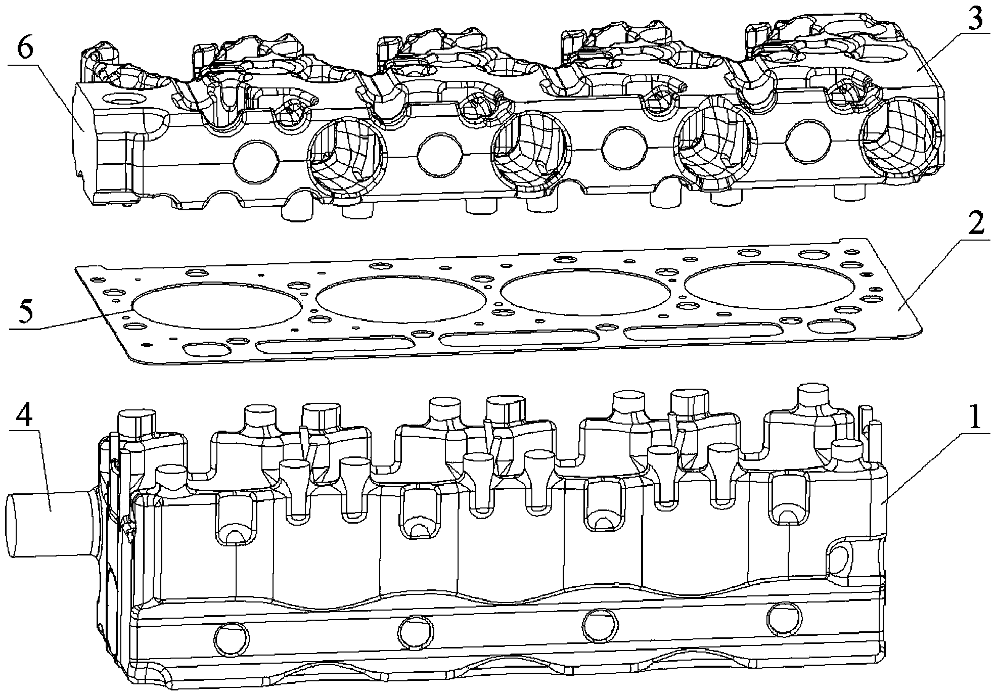
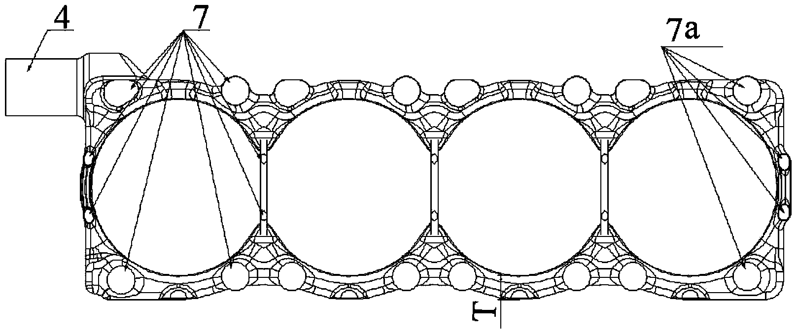
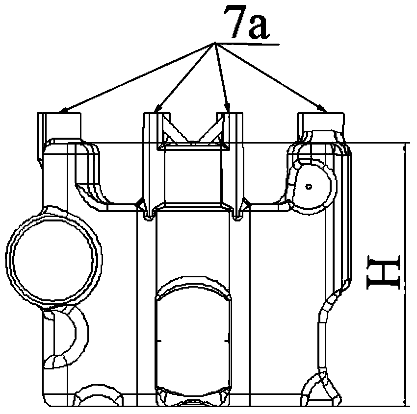
[0023] Such as Figure 1 to Figure 6 As shown, the engine cooling water jacket according to the specific embodiment of the present invention includes: a cylinder block water jacket 1, a cylinder head water jacket 3 corresponding to the cylinder block water jacket 1, and a gap between the cylinder block water jacket 1 and the cylinder head water jacket 3 cylinder head gasket 2.

[0024] The water jacket 1 of the cylinder b...


PUM


Abstract

The invention discloses an engine cooling water jacket. The engine cooling water jacket comprises a cylinder block water jacket body, a cylinder head gasket and a cylinder head water jacket body, wherein a water inlet is formed in the front end of the cylinder block water jacket body, water feeding holes are formed around each cylinder, the water feeding hole located at the rearmost end of each cylinder is a main water feeding hole, the cylinder head water jacket body corresponds to the cylinder block water jacket body, a water outlet is formed in the front end of the cylinder head water jacket body, water inlets corresponding to the water feeding holes in position are formed in the cylinder head water jacket body, and the water inlet located at the rearmost end of each cylinder is a main water inlet; the cylinder head gasket is arranged between the cylinder block water jacket body and the cylinder head water jacket body, a plurality of round holes are formed in the length direction of the cylinder head gasket, water passing holes are formed around each round hole, and each water passing hole located at the rearmost end is a main water passing hole; the water passing holes become larger gradually and sequentially from the front end to the rear end, and the size of each main water feeding hole is identical with that of the corresponding main water passing hole and that of the corresponding main water inlet. By the adoption of the engine cooling water jacket, the flowing speed of cooling liquid in the cylinder block water jacket body can be effectively increased, the temperatures of different parts of the cylinder block tend to be consistent, and the service life of an engine is prolonged.

Description

technical field [0001] The invention relates to the field of engines, in particular to an engine cooling water jacket. Background technique [0002] The flow direction of the traditional engine water jacket coolant is: the coolant output by the engine water pump enters from the water inlet of the cylinder block, flows around the cylinder liner and flows to both sides of the water jacket of the cylinder block, and then the coolant of each cylinder of the cylinder block passes through the cylinder head gasket respectively. The through-holes set on the cylinder head that match the water outlet holes on the top surface of the cylinder block and the water inlet holes on the bottom surface of the cylinder head flow to the water jacket of the cylinder head, and finally flow out from the water outlet of the cylinder head together, and return to the water tank through relevant pipelines. [0003] The existing technology mainly has the following problems: 1. The height H and thickness...

Claims


Application Information

Patent Timeline
Patent Type & Authority Applications(China)
IPC IPC(8): F02F1/16
CPCF02F1/16F02F1/40
Inventor 张雷董家枝梁德浦余晓强石峰
Owner GUANGXI YUCHAI MASCH CO LTD
Why Eureka
Try Eureka