
System, method, and article of manufacture for adjusting CO emission levels at predetermined locations in a boiler system

a technology of predetermined locations and boiler systems, applied in the direction of digital computer details, combustion measurement, combustion control, etc., can solve the problems of increasing total co emissions and local co concentrations above the threshold level, and achieve the effect of decreasing the co level, and increasing the a/f ratio

Inactive Publication Date: 2009-09-01
GENERAL ELECTRIC CO
View PDF15 Cites 4 Cited by
  • Summary
  • Abstract
  • Description
  • Claims
  • Application Information

AI Technical Summary

Benefits of technology

"The patent describes a method for adjusting the levels of carbon dioxide (CO) in a boiler system. The method involves using sensors to measure CO levels at various locations in the boiler system. By analyzing these measurements, the system can determine which burners are contributing to the high CO levels and which locations in the system have the highest CO levels. The system can then adjust the operation of these burners to decrease the CO levels at those locations. This method can help to improve the efficiency of the boiler system and reduce emissions of CO, which is a harmful gas."

Problems solved by technology

Further, the variance of CO levels in the boiler system can result in increased total CO emissions and local CO concentrations above the threshold level.

Method used


Image

  • System, method, and article of manufacture for adjusting CO emission levels at predetermined locations in a boiler system
  • System, method, and article of manufacture for adjusting CO emission levels at predetermined locations in a boiler system
  • System, method, and article of manufacture for adjusting CO emission levels at predetermined locations in a boiler system

Examples


Embodiment Construction

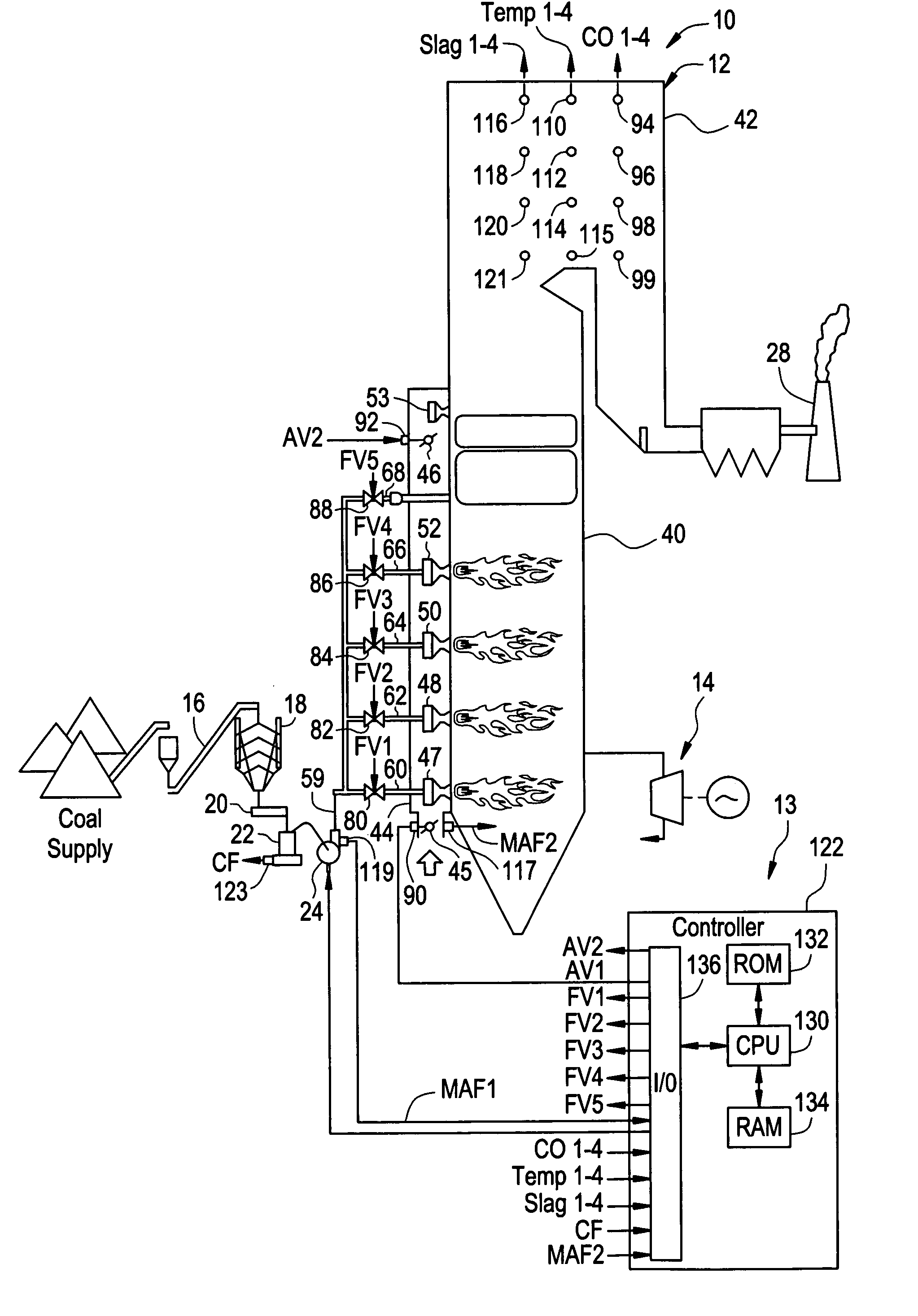
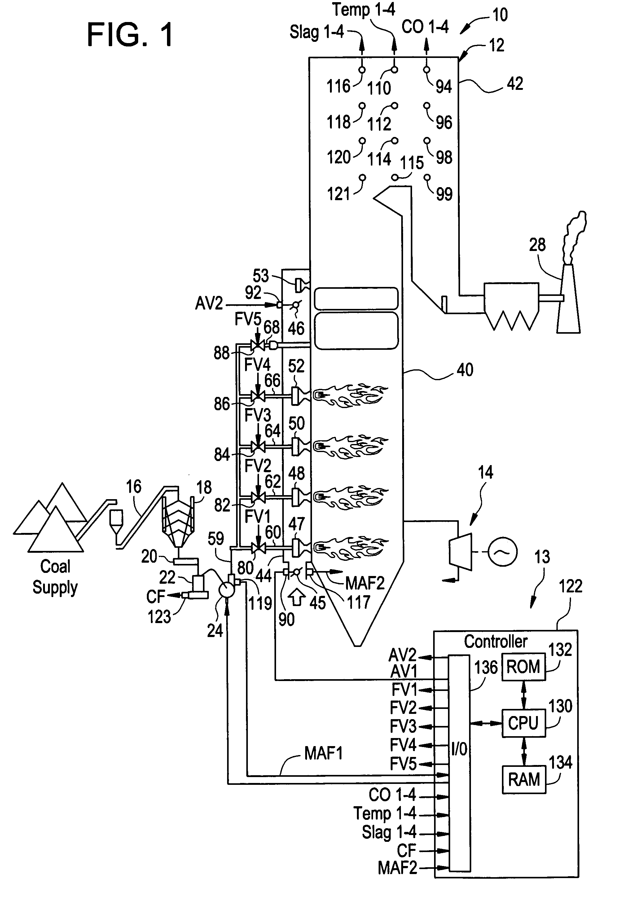
[0014]Referring to FIG. 1, a power generation system 10 for generating electrical power is illustrated. The power generation system 10 includes a boiler system 12, a control system 13, a turbine generator 14, a conveyor 16, a silo 18, a coal feeder 20, a coal pulverizer 22, an air source 24, and a smokestack 28.

[0015]The boiler system 12 is provided to burn an air-coal mixture to heat water to generate steam therefrom. The steam is utilized to drive the turbine generator 14, which generates electricity. It should be noted that in an alternative embodiment, the boiler system 12 could utilize other types of fuels, instead of coal, to heat water to generate steam therefrom. For example, the boiler system 12 could utilize any conventional type of hydrocarbon fuel such as gasoline, diesel fuel, oil, natural gas, propane, or the like. The boiler system 12 includes a furnace 40 coupled to a back path portion 42, an air intake manifold 44, burners 47, 48, 50, 52, an air port 53, and conduit...


PUM


Abstract

A system, a method, and an article of manufacture for adjusting CO emission levels in predetermined locations in a boiler system are provided. The boiler system has a plurality of burners and a plurality of CO sensors disposed therein. The system determines locations within the boiler system that have relatively high CO levels utilizing the plurality of CO sensors and then adjusts A / F ratios of burners affecting those locations to decrease the CO levels at the locations.

Description

CROSS REFERENCE TO RELATED APPLICATIONS[0001]This application is related to the following United States Patent Applications filed contemporaneously herewith: SYSTEM AND METHOD FOR DECREASING A RATE OF SLAG FORMATION AT PREDETERMINED LOCATIONS IN A BOILER SYSTEM, Ser. No. 11 / 290,759; and SYSTEM, METHOD, AND ARTICLE OF MANUFACTURE FOR ADJUSTING TEMPERATURE LEVELS AT PREDETERMINED LOCATIONS IN A BOILER SYSTEM, Ser. No. 11 / 290,244 which are incorporated by reference herein in their entirety.BACKGROUND OF THE INVENTION[0002]Fossil-fuel fired boiler systems have been utilized for generating electricity. One type of fossil-fuel fired boiler system combusts an air / coal mixture to generate heat energy that increases a temperature of water to produce steam. The steam is utilized to drive a turbine generator that outputs electrical power.[0003]A by-product of combusting an oxygen and a hydrocarbon-based fuel mixture, such an air / coal mixture, is carbon monoxide (CO). One objective of a control...

Claims


Application Information

Patent Timeline
Patent Type & Authority Patents(United States)
IPC IPC(8): F23N5/00
CPCF22B35/00F23D1/02F23D23/00F23N5/003F23N1/022F23N2041/10F23N2025/10F23N2037/02F23N2225/10F23N2241/10F23N2237/02
Inventor WIDMER, NEIL COLINTAWARE, AVINASH VINAYAKCHONG, IVY WAI MAN
Owner GENERAL ELECTRIC CO
Learn More