
System having a secondary current generating assembly for the secondary conversion into electricity of exhaust gas heat from a primary current generating assembly

a technology of primary current generating assembly and secondary current, which is applied in the direction of gas/liquid distribution and storage, vehicle components, cranes, etc., can solve the problems of performance reduction effect, insufficient regulation and adaptation of previously known etc. installations to the changing operating conditions of primary thermal engines, etc., and achieves improved efficiency, improved emission levels, and further reduction of fuel consumption.

Active Publication Date: 2020-02-20
KONECRANES GLOBAL
View PDF0 Cites 5 Cited by
  • Summary
  • Abstract
  • Description
  • Claims
  • Application Information

AI Technical Summary

Benefits of technology

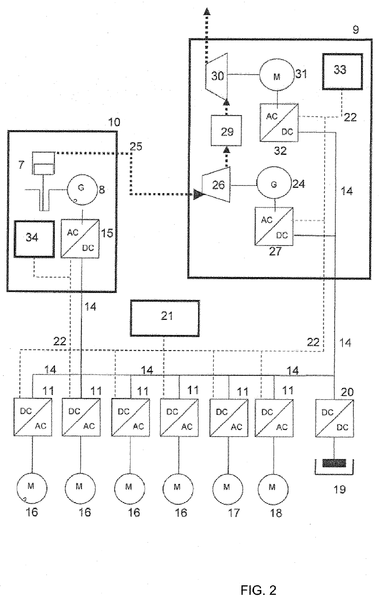
The present invention provides a vehicle for handling freight containers with a system for improving efficiency and reducing fuel consumption. The vehicle has a primary current generating assembly with a thermal engine and a secondary current generating assembly with an electric turbo compound installation. The secondary current generating assembly includes an exhaust gas turbine, a compressor, and a secondary inverter and frequency converter. The system allows for control and regulation of energy flows and can be adapted to changing operating conditions of the thermal engine and exhaust gas post-treatment system. The secondary current generating assembly can be retrospectively mounted on the already operational primary thermal engine without needing any changes or adjustments. The secondary current generating assembly operates according to the inverted Brayton cycle (IBC) and is less expensive and more efficient than previously known waste heat recovery systems. The rotational speeds of the secondary generator and compressor can be adjusted for optimal performance and adaptability to changing operating states.

Problems solved by technology

Previously known ETC installations can also often be only insufficiently regulated and adapted to the changing operating conditions of the primary thermal engine and the exhaust gas system thereof, such as e.g. an exhaust turbocharger, exhaust gas post-treatment system (SCR), exhaust gas recovery, soot particle filter etc.
The previously known ETC installations mostly have the disadvantage that the pressure difference which builds up via the downstream turbine generates a counter-pressure on the exhaust gas system of the primary thermal engine and therefore has a performance-reducing effect.

Method used


Image

  • System having a secondary current generating assembly for the secondary conversion into electricity of exhaust gas heat from a primary current generating assembly
  • System having a secondary current generating assembly for the secondary conversion into electricity of exhaust gas heat from a primary current generating assembly

Examples


Embodiment Construction

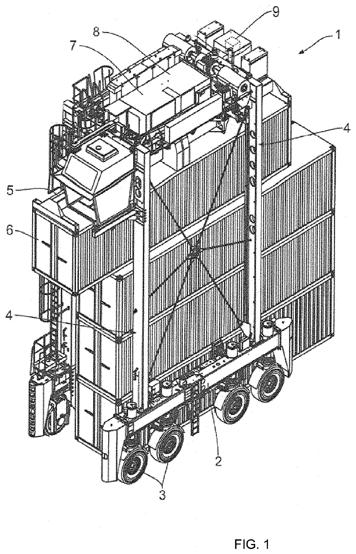
[0023]FIG. 1 shows a perspective view of a gantry lift stacker 1 in accordance with an exemplary embodiment of the invention, also referred to as a straddle carrier or van carrier. The gantry lift stacker 1 comprises two running gear unit supports 2 orientated in a travel direction of the gantry lift stacker 1, on which supports in each case four individual wheels 3 are disposed. The running gear unit supports 2 are disposed in parallel with each other and in a common horizontal plane. On an upper side facing away from the wheels 3 the two running gear unit supports 2 are connected to each other by two substantially U-shaped gantry frames 4. As seen in a forwards travel direction of the gantry lift stacker 1, the gantry frames 4 are disposed or erected on a front end of the running gear unit supports 2 and on a rear end of the running gear unit supports 2. The gantry lift stacker 1 comprises a spreader 5 which can be raised and lowered vertically and is guided within the two gantry ...


PUM


Abstract

A system having a primary current generating assembly includes a primary thermal engine and a secondary current generating assembly, in particular an electric turbo compound installation, for the secondary conversion into electricity of exhaust gas heat from the primary current generating assembly. The secondary current generating assembly includes an exhaust gas turbine arranged in an exhaust gas stream of the primary thermal engine, and the exhaust gas turbine drives an electric secondary generator. In order to improve efficiency, and in particular to reduce fuel consumption, it is proposed that an exhaust gas cooler followed by a compressor are arranged in the exhaust gas stream downstream of the exhaust gas turbine, the compressor being driven by an electric motor and the rotational speeds of the compressor and the exhaust gas turbine are controlled by a process control system. The disclosed invention also relates to a vehicle equipped therewith.

Description

CROSS REFERENCE TO RELATED APPLICATIONS[0001]The present application is a § 371 national stage of International Application PCT / EP2017 / 077335, filed Oct. 25, 2017, which claims priority benefit of German Pat. Application DE 10 2016 120 764.0, filed Oct. 31, 2016.FIELD OF THE INVENTION[0002]The invention relates to a system with a primary current generating assembly, in particular for a vehicle for handling freight containers.[0003]European patent EP 2 759 509 B1 discloses a gantry lift stacker having a hybrid drive which, in addition to an electric generator, has an internal combustion engine for gas or diesel. A so-called electric turbo compound (ETC) installation is connected downstream of the hybrid drive to provide secondary conversion into electricity of exhaust gas energy of the internal combustion engine. The ETC installation contains, in addition to an exhaust gas turbine for generation of mechanical energy from the exhaust gas energy, a generator for generating electrical e...

Claims


Application Information

Patent Timeline
Patent Type & Authority Applications(United States)
IPC IPC(8): F02G5/02B66C19/00F02C6/00B66C13/22B60L50/15F01N5/04
CPCF17C2221/033F01N5/04B66C19/007F17C2223/0161B66C13/22F02C6/006B60L2200/42F02G5/02B60L50/15B60L2220/42B66C13/18B60L50/50Y02E20/14Y02T10/12Y02T10/64Y02T10/70
Inventor BAUER, REINHARD
Owner KONECRANES GLOBAL
Learn More