Fully-sealed scroll compressor and assembly method thereof

A technology for scroll compressors and assembly methods, applied in the field of scroll compressors, can solve problems such as poor coaxiality of main and auxiliary bearings, increased production costs, expensive welding equipment, etc., to reduce deformation and reduce assembly and the cost of assembly equipment, and the effect of improving production efficiency

Inactive Publication Date: 2015-01-21
HEFEI SANSONG HOT & COLD TECH
View PDF5 Cites 1 Cited by
  • Summary
  • Abstract
  • Description
  • Claims
  • Application Information

AI Technical Summary

Problems solved by technology

[0007] The technical problem to be solved by the present invention is to overcome the deficiencies of the prior art and provide a fully enclosed scroll compressor and its assembly method. In the present invention, the main and auxiliary bearing supports are fixed on the compressor shell through interference , because the shell itself has a good inner diameter cylindricity, the main and service bearings are supported and assembled using special molds to ensure that the main and service bearings are coaxial with the inner diameter of the shell, thereby achieving the purpose of the main and service bearings being coaxial, and solving the problem In the prior art, the welding method of the main and auxiliary bearings has a certain deformation during the welding process, which leads to the problem of poor coaxiality of the main and auxiliary bearings, and at the same time solves the problem of increased production costs caused by expensive welding equipment in the prior art. The present invention The structure is compact, the main bearing support and auxiliary bearing are fixed by interference method instead of conventional welding method, which simplifies the assembly equipment and reduces the assembly cost of the compressor on the basis of reducing the support deformation

Method used


Image

  • Fully-sealed scroll compressor and assembly method thereof
  • Fully-sealed scroll compressor and assembly method thereof
  • Fully-sealed scroll compressor and assembly method thereof

Examples


Embodiment Construction

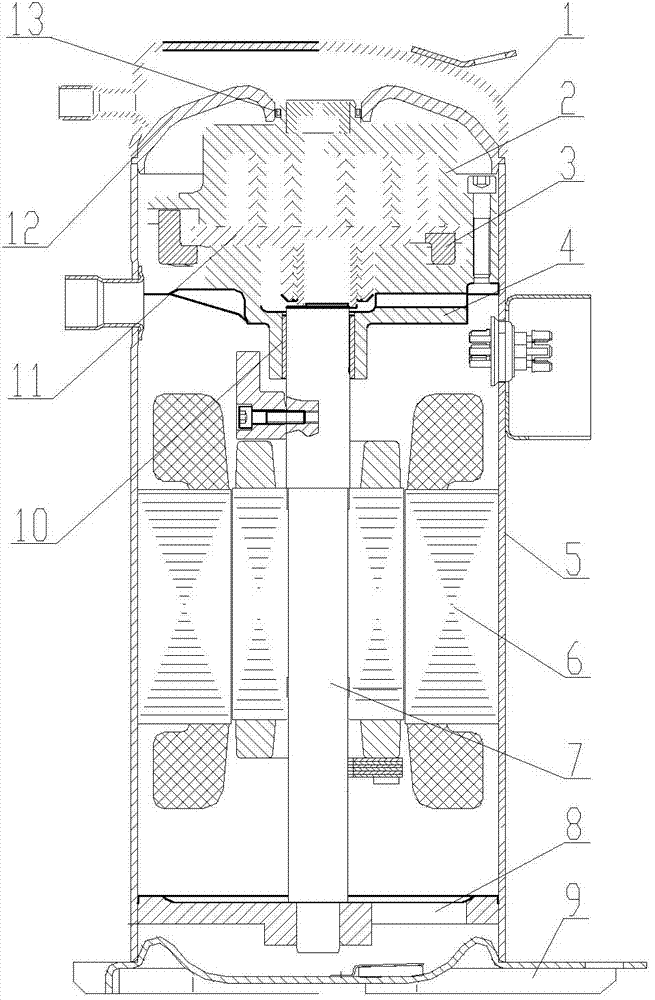
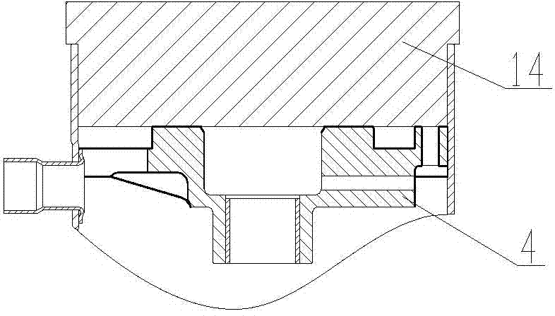
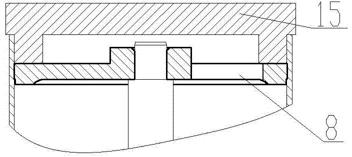
[0033] Such as figure 1 As shown, a fully enclosed scroll compressor includes an upper cover 1, a fixed scroll 2, an Oldham ring 3, a main bearing support 4, a casing 5, a driving crankshaft assembly 7, a rotating motor stator 6, and an auxiliary bearing 8 . The lower cover 9 fixed on the lower end of the housing 5, the main bearing 10, the movable scroll 11, the high and low pressure isolation plate 12, and the sealing ring 13 are characterized in that:

[0034] The movable scroll 11 driven by the crankshaft assembly 7 and the fixed scroll 2 cooperate with each other to form at least one compression chamber, the Oldham ring 3 is arranged between the fixed scroll 2 and the main bearing support 4, and the Oldham The ring 3 cooperates with the fixed scroll 2 and the movable scroll 11, so that the movable scroll 11 can only translate relative to the fixed scroll 2, and the crankshaft 7 drives the movable scroll 11 along the track Plane movement, so as to complete the suction, co...


PUM


Abstract

The invention discloses a fully-sealed scroll compressor and an assembly method thereof and relates to the field of scroll compressors. The scroll compressor comprises an upper cover, a static scroll, a crossed ring, a main bearing support, a shell, a motor stator with a motor rotor, an auxiliary bearing, a lower cover, a main bearing, a movable scroll, a high-low-pressure isolation board and a seal ring, wherein the motor stator is used for driving a crankshaft to rotate; the lower cover is fixed at the lower end of the shell; the moveable and static scrolls are matched with each other so as to form at least one compressing cavity; the main bearing support is fixed at the upper end in the shell in an interference manner; an auxiliary bearing support is fixed at the lower end in the shell in an interference manner and acts as an auxiliary bearing; the main and auxiliary bearings are coaxial. The fully-sealed scroll compressor is compact in structure; the main and auxiliary bearing supports are fixed in the interference manner, not in a normal welding manner; on the premise that the deformation of the supports is alleviated, assembly devices are simplified and the assembly cost of the compressor is lowered.

Description

technical field [0001] The invention relates to the field of scroll compressors, in particular to a fully enclosed scroll compressor and an assembly method thereof. Background technique [0002] Scroll compressors are increasingly widely used in the refrigeration industry. Among the existing scroll compressors, there are fixed scrolls with helical scroll teeth, and fixed scrolls with spiral scroll teeth matched with the fixed scroll. The movable vortex, which moves between the movable vortex and the upper support, respectively cooperates with the movable and fixed vortexes and restricts them to move in relative translation. There are multiple compression chambers, and the motor drives the crankshaft to drive the movable scroll to revolve along its orbit, so as to complete the suction, compression and discharge of gas, so as to achieve the purpose of compressing the refrigerant. [0003] For a fully enclosed compressor, the scroll parts are installed inside the compressor ca...

Claims


Application Information

Patent Timeline
Patent Type & Authority Applications(China)
IPC IPC(8): F04C18/02B23P21/00
CPCF04C18/02B23P21/00F04C2230/60
Inventor 杜希刚
Owner HEFEI SANSONG HOT & COLD TECH
Why Eureka
Try Eureka