
Self-steering proportional control valve block and navigation hydraulic system based on self-steering proportional control valve block

A proportional control valve and automatic steering technology, applied in fluid steering mechanism, fluid pressure actuator, servo motor, etc., can solve the problems of system leakage, large heat loss, heat generation, etc., and achieve high control precision and fast response speed , the effect of small heat loss

Inactive Publication Date: 2015-01-21
CHINA AGRI UNIV
View PDF10 Cites 20 Cited by
  • Summary
  • Abstract
  • Description
  • Claims
  • Application Information

AI Technical Summary

Problems solved by technology

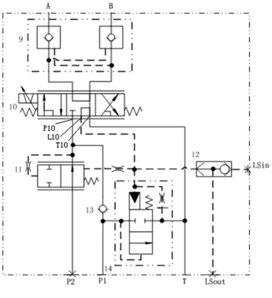
[0004] In order to overcome the problems that the existing agricultural machinery automatic steering system has poor versatility, large heat loss, serious heat generation, serious system leakage, and is not suitable for long-term work, and further improve the safety and reliability of the agricultural machinery automatic steering system, Control accuracy and quick response, the present invention proposes an automatic steering proportional control valve block suitable for various automatic steering systems and a navigation hydraulic system based on the valve block

Method used


Image

  • Self-steering proportional control valve block and navigation hydraulic system based on self-steering proportional control valve block
  • Self-steering proportional control valve block and navigation hydraulic system based on self-steering proportional control valve block
  • Self-steering proportional control valve block and navigation hydraulic system based on self-steering proportional control valve block

Examples


specific Embodiment 1

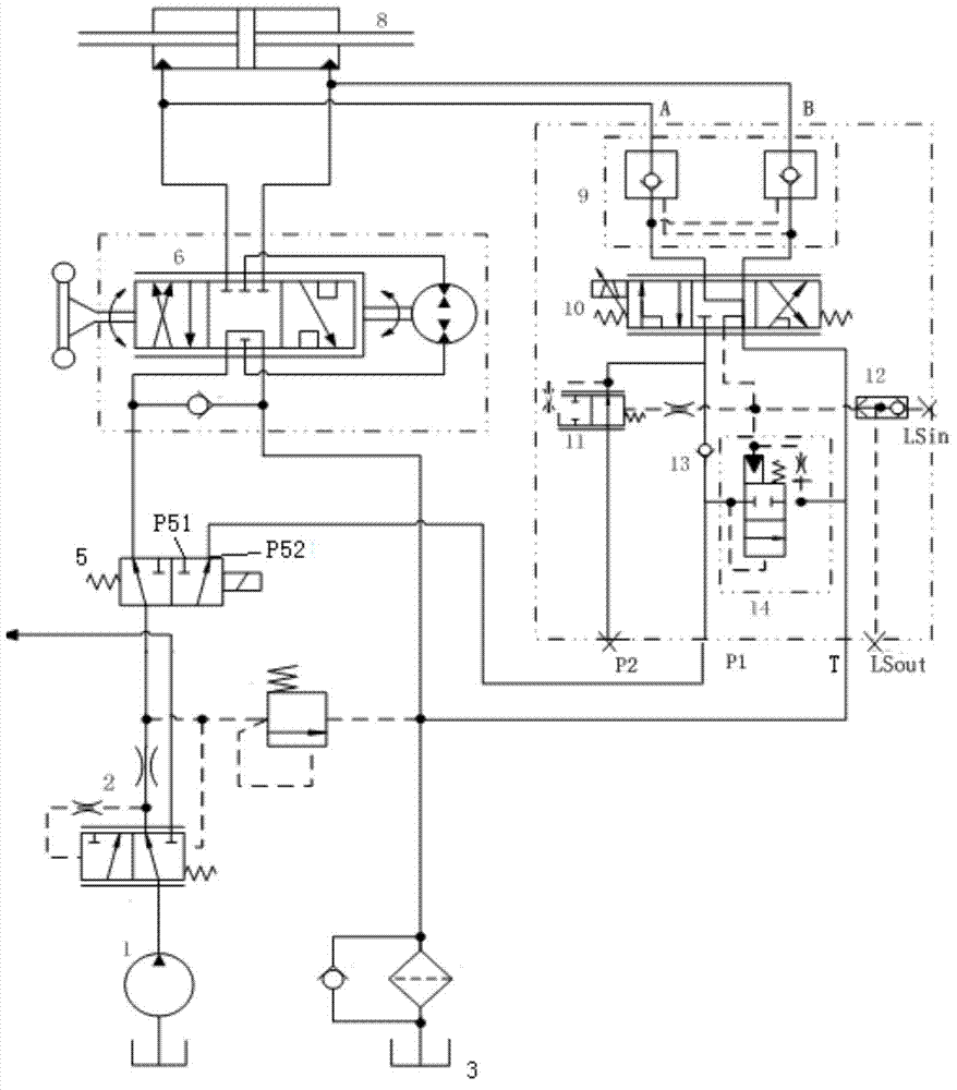
[0055] Such as figure 2 As shown, the automatic steering proportional control valve block is connected in parallel with the open-type full hydraulic steering gear to form a navigation hydraulic system based on this automatic steering proportional control valve block. The specific connection method is:

[0056] The second pressure oil input port P2, the first load pressure feedback port LS in and the second load pressure feedback port LS out sealed;

[0057] The first steering hydraulic cylinder interface A and the second steering hydraulic cylinder interface B are respectively connected to the left and right chambers of the steering hydraulic cylinder 8 of the navigation hydraulic system;

[0058] The first pressure oil input port P1 is connected to the right oil outlet P52 of the reversing valve 5, and the left oil outlet P51 of the reversing valve 5 is connected to the oil inlet of the open-ended steering gear servo valve 6 of the open-ended full hydraulic steering gear. ...

specific Embodiment 2

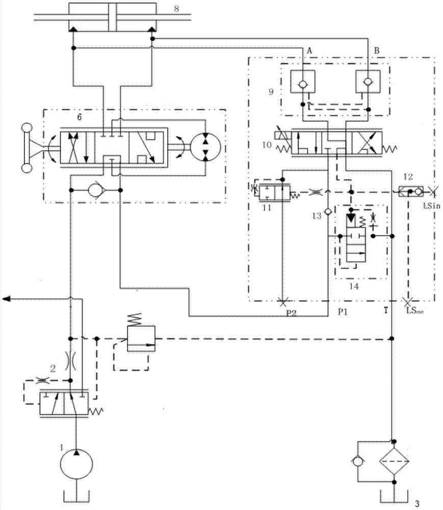
[0060] Such as image 3 As shown, the automatic steering proportional control valve block is connected in series with the open-ended full hydraulic steering gear to form a navigation hydraulic system based on this automatic steering proportional control valve block. The specific connection method is as follows:

[0061] The second pressure oil input port P2, the first load pressure feedback port LS in and the second load pressure feedback port LS out sealed;

[0062] The first steering hydraulic cylinder interface A and the second steering hydraulic cylinder interface B are respectively connected to the left and right chambers of the steering hydraulic cylinder 8 of the navigation hydraulic system;

[0063] The oil return port T of the automatic steering proportional control valve block communicates with the oil return tank 3 of the navigation hydraulic system through a filter;

[0064] The first pressure oil input port P1 communicates with the oil return port of the open-e...

specific Embodiment 3

[0067] Such as Figure 4 As shown, the automatic steering proportional control valve block is connected in parallel with the load sensing closed-center full hydraulic steering gear to form a navigation hydraulic system based on this automatic steering proportional control valve block. The specific connection method is as follows:

[0068] The first pressure oil input port P1 is sealed;

[0069] The first steering hydraulic cylinder interface A and the second steering hydraulic cylinder interface B are respectively connected to the left and right chambers of the steering hydraulic cylinder 8 of the navigation hydraulic system;

[0070] The oil return port T of the automatic steering proportional control valve block communicates with the oil return tank 3 of the navigation hydraulic system;

[0071] The oil inlet of the single stable diverter valve 2 is connected with the hydraulic pump 1 . The oil outlet of the single stable diverter valve 2 is connected to two parallel pipel...


PUM


Abstract

The invention belongs to self-steering systems for automatic navigation of agricultural machines and particularly relates to a self-steering proportional control valve block and a navigation hydraulic system based on the self-steering proportional control valve block. The valve block is provided with a first pressure oil feed inlet, a second pressure oil feed inlet, an oil return port, a first steering hydraulic cylinder connector, a second steering hydraulic cylinder connector, a first load pressure feedback port and a second load pressure feedback port and comprises a load sensing oil port and a three-position and five-way proportional directional valve, a fixed-differential reducing valve, a one-way valve and a differential pressure type overflow valve, wherein the median function of the three-position and five-way proportional directional valve is in the Y type. An automatic navigation system can be formed by connecting the valve block with a core-opening full-hydraulic steering gear or a core-closing full-hydraulic steering gear or a load sensing type core-closing full-hydraulic steering gear. When the navigation system works, the quantity of oil flowing into the steering hydraulic cylinder is only related to the opening degree of the three-position and five-way proportional directional valve and is basically not affected by the change of the load of the steering hydraulic cylinder. According to the self-steering proportional control valve block, heat loss is small, the control accuracy is high, and the response speed is high.

Description

technical field [0001] The invention belongs to an automatic steering system for automatic navigation of agricultural machinery, in particular to an automatic steering proportional control valve block and a navigation hydraulic system based on the valve block. Background technique [0002] At present, most of the farmland operations are large-scale inter-row operations. This operation method requires the agricultural machine driver to strictly ensure that the agricultural machine's operating track is parallel to the crop row during the driving process. Therefore, the driver must be skilled in driving and have a high degree of concentration, but this can easily lead to driver fatigue driving, resulting in a decrease in operating accuracy, and even may lead to safety accidents. Even the best agricultural machinery operator can achieve the highest control accuracy of only 10cm when farming in the field, and the accuracy will be greatly reduced after working for a long time. Si...

Claims


Application Information

Patent Timeline
Patent Type & Authority Applications(China)
IPC IPC(8): F15B13/04F15B11/02B62D5/08
CPCB62D5/06B62D5/08F15B11/02F15B13/0401
Inventor 毛恩荣朱忠祥谭井泉刘进一
Owner CHINA AGRI UNIV
Learn More