
LED lamp

A technology of LED lights and fins, applied in the field of light sources, can solve problems affecting the luminous efficiency and life of LED lights

Active Publication Date: 2015-01-21
东莞市闻誉实业有限公司
View PDF8 Cites 9 Cited by
  • Summary
  • Abstract
  • Description
  • Claims
  • Application Information

AI Technical Summary

Problems solved by technology

During the working process of the LED lamp, a large amount of heat gathers in the LED lamp. If the heat dissipation efficiency is not improved, the temperature of the LED chip will be too high, which will seriously affect the luminous efficiency and life of the LED lamp.

Method used


Image

  • LED lamp
  • LED lamp
  • LED lamp

Examples


Embodiment Construction

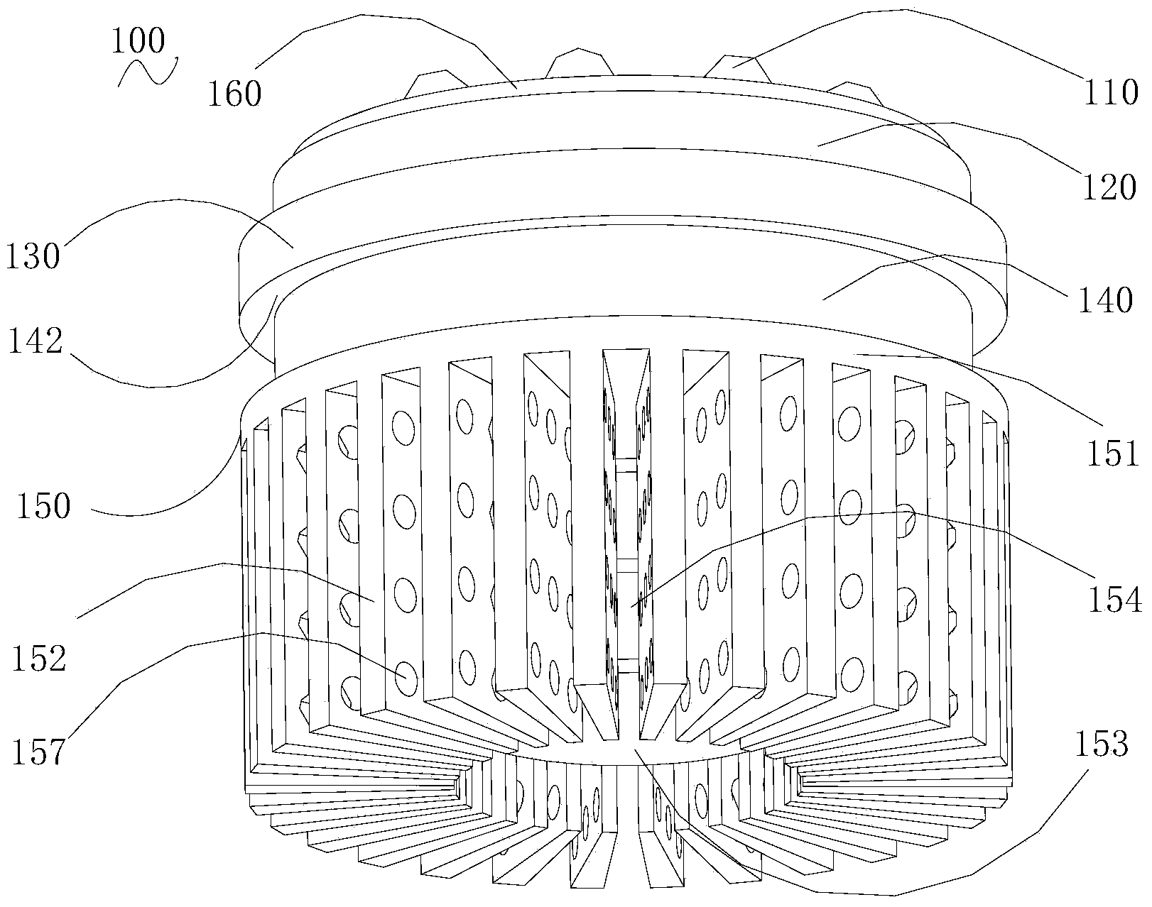
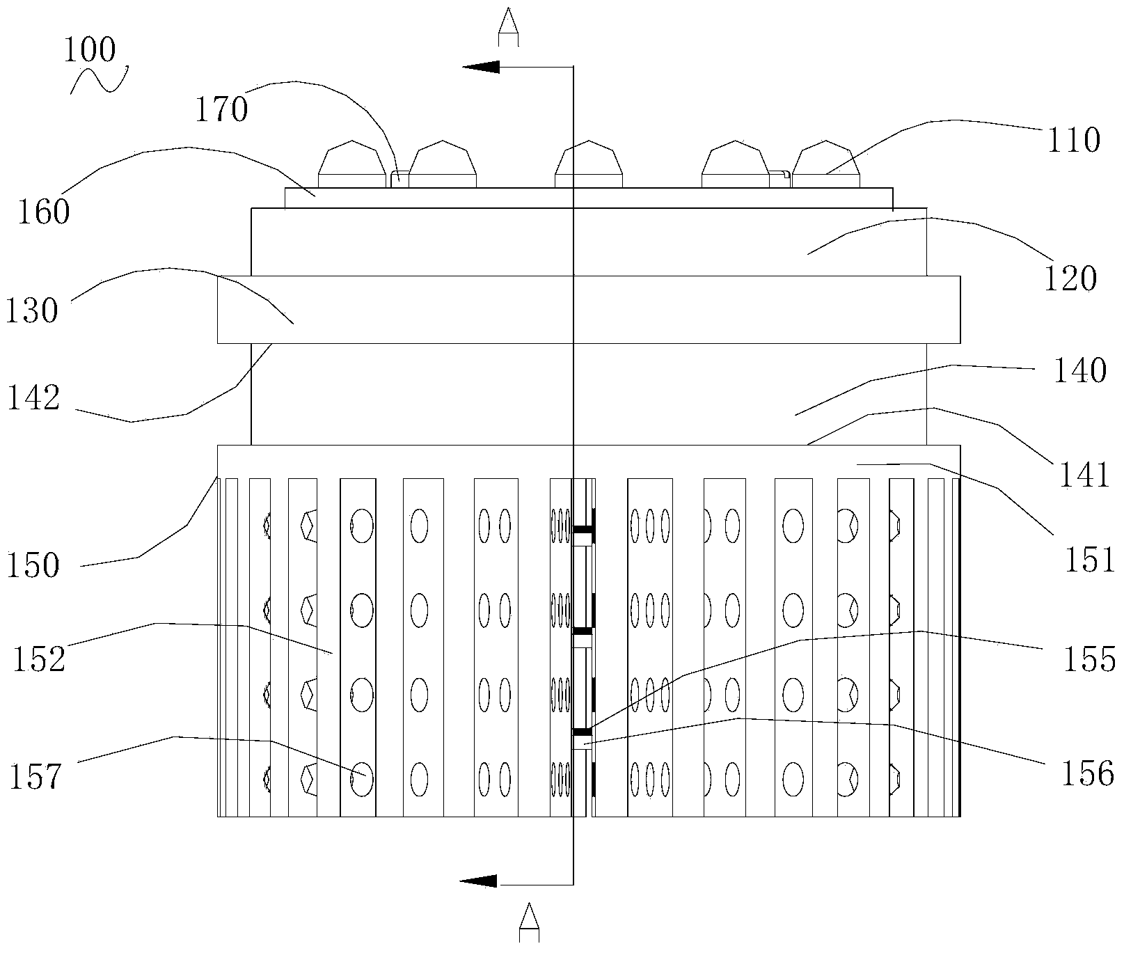
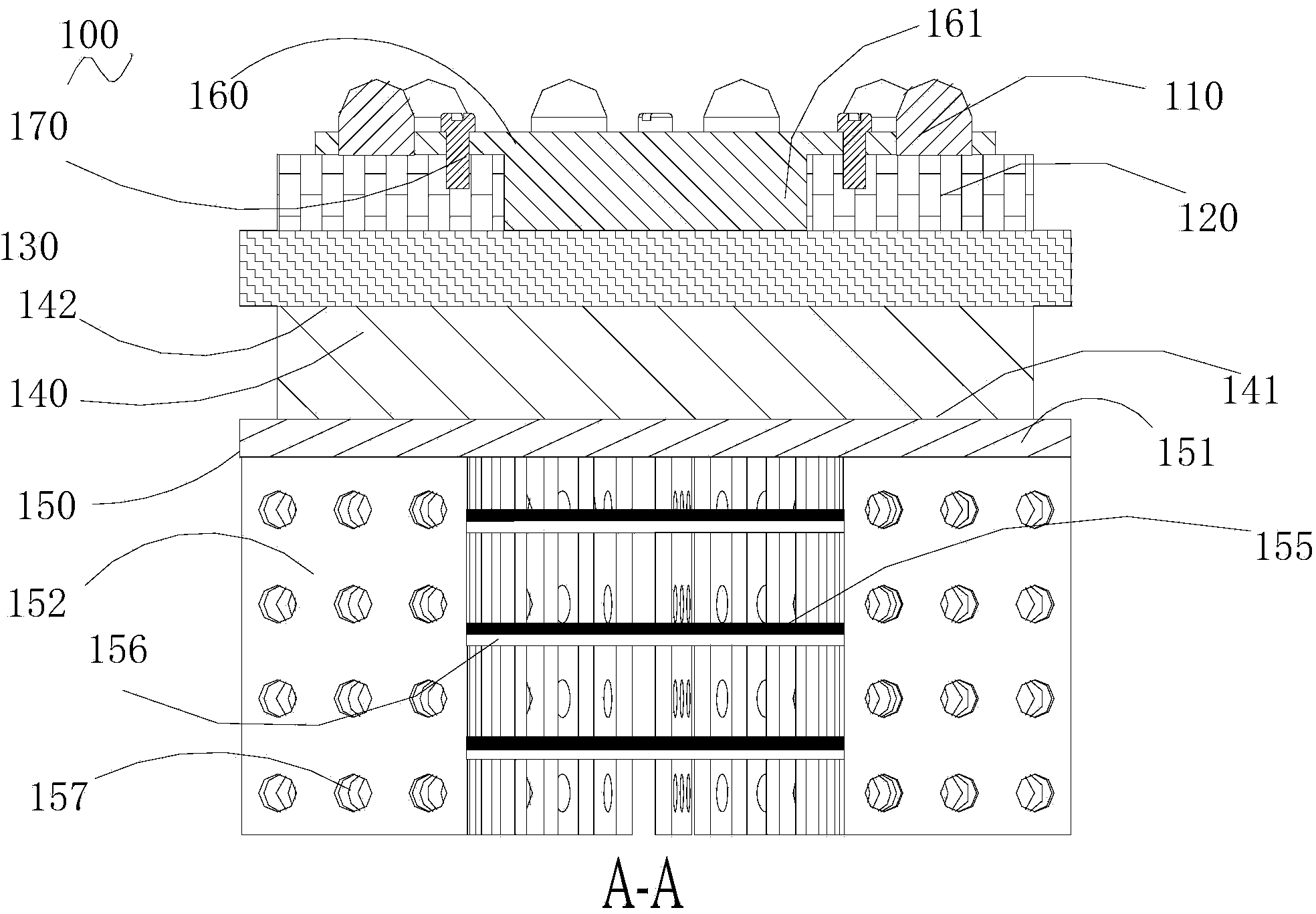
[0020] Such as Figure 1-Figure 3 as shown, figure 1 It is a schematic structural diagram of an LED lamp according to an embodiment of the present invention, figure 2 for figure 1 The front view of the LED light in, image 3 for figure 2 A-A sectional view of the LED lamp in the medium.

[0021] The LED lamp 100 includes: an LED light emitting unit 110 , a circuit board 120 , a heat transfer plate 130 for transferring heat, a semiconductor cooling sheet 140 and a heat sink 150 connected in sequence. The LED lamp 100 also includes a heat transfer sheet 160 , and the heat transfer sheet 160 is closely mounted on the side of the circuit board 120 with the LED light emitting unit 110 . In this embodiment, the heat transfer sheet 160 is provided with a sleeve hole 163 corresponding to the LED light emitting unit 110 , so that it can be closer to the heat sink of the LED light emitting unit 110 to absorb heat faster. The heat transfer sheet 160 and the circuit board 120 are ...


PUM


Abstract

An LED lamp comprises LED luminous units, a circuit board, a heat transfer board, a semiconductor refrigerating plate, a heat sink, a heat transfer plate and a heat transfer post. The LED luminous units, the circuit board, the heat transfer board, the semiconductor refrigerating plate and the heat sink are connected in sequence; the circuit board is used for mounting of the LED luminous units; the heat transfer board is used for transferring heat; the heat transfer plate is closely mounted to one sides of the LED luminous units; the heat transfer post which is protruded is arranged in the middle of the heat transfer plate; the circuit board is provided with a via hole corresponding to the heat transfer post, and the heat transfer post penetrates the via hole to be connected with the heat transfer board. Further, the heat sink comprises a base plate and a plurality of fins mounted on the base plate; the fins on the base plate encircle to form a cavity; a gap is formed between every two adjacent fins; and the cavity is communicated with the gaps. A plurality of piezoelectric oscillator plates are parallelly arranged in the cavity along a direction perpendicular to the fins and are connected with the fins. After power on, the piezoelectric oscillator plates bound in the cavity oscillate to compress air in the cavity to exhaust high-heat air in the cavity rapidly from the gaps, so that heat is dissipated and radiating efficiency of the LED lamp is improved.

Description

technical field [0001] The invention relates to a light source, in particular to an LED lamp. Background technique [0002] LED (Light Emitting Diode), that is, semiconductor electric light source, light-emitting diode, also known as semiconductor lamp, is a kind of electric light source without filament, which directly converts electrical energy into light energy. [0003] As a solid-state lighting source, LED lights have become a revolution in the history of human lighting because of their advantages such as long service life, high luminous efficiency, multiple light colors, small size, safety and environmental protection. Theoretically, the luminous efficiency of LED lamps is very high, but in the current LED lamps, the heat transfer plate transfers the heat generated by the LED light-emitting unit to the semiconductor cooling sheet, and then the semiconductor cooling sheet transfers the heat to the heat sink. The sheet dissipates heat into the air, thereby reducing the ...

Claims


Application Information

Patent Timeline
Patent Type & Authority Applications(China)
IPC IPC(8): F21V29/503F21V29/54F21V29/77F21V29/85F21Y101/02
CPCF21K9/20F21Y2105/10F21Y2115/10
Inventor 叶伟炳
Owner 东莞市闻誉实业有限公司
Learn More