Heat exchange tube, manufacturing method of heat exchange tube and heat exchanger with heat exchange tube

A technology of heat exchange tubes and tubes, which is applied in the field of heat exchange, and can solve problems such as poor heat exchange efficiency, increased gas impedance, and fast passing speed

Inactive Publication Date: 2015-01-21
WUXI TRS HEAT EXCHANGER CO LTD
View PDF8 Cites 9 Cited by
  • Summary
  • Abstract
  • Description
  • Claims
  • Application Information

AI Technical Summary

Problems solved by technology

At present, the heat exchange tubes sold in the market mainly include circular tubes with a smooth tube structure and circular tubes with a spiral structure. The circular tubes with a bare tube structure have poor heat transfer efficiency due to the fast passage of hot gas and the short contact time with the refrigerant.
Due to the existence of the helical structure, the hot gas generates turbulent flow when passing through the heat exchange tube, which increases the residence time of the hot

Method used


Image

  • Heat exchange tube, manufacturing method of heat exchange tube and heat exchanger with heat exchange tube
  • Heat exchange tube, manufacturing method of heat exchange tube and heat exchanger with heat exchange tube

Examples


Embodiment 1

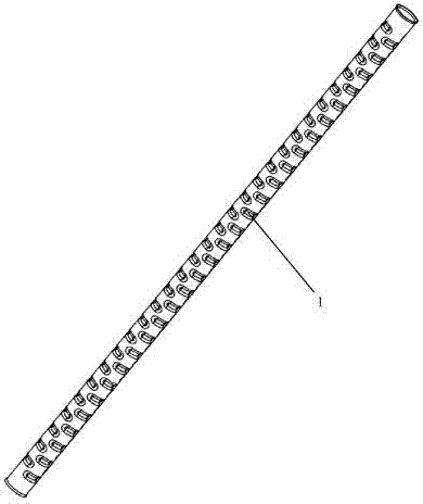
[0021] Such as figure 1 As shown, the present invention provides a heat exchange tube. Four rows of arc-shaped grooves are pressed on the surface of the heat exchange tube along the length direction. Each row of arc-shaped grooves is at the same horizontal position. The arc length of the arc-shaped grooves 0.25 times the circumference of the heat exchange tube section, the depth is 0.15-0.25 times the diameter of the heat exchange tube section circle, and the width is 0.15-0.25 times the heat exchange tube section circle diameter. The circumferential direction of the tube is staggered by 90 degrees, the distance between two adjacent arc-shaped grooves on the same row of arc-shaped grooves is equal to the diameter of the cross-sectional circle of the heat exchange tube, and the stagger between two adjacent rows of arc-shaped grooves is 0.5 times The cross-sectional diameter of the heat exchange tube.

Embodiment 2

[0023] A method of manufacturing a heat exchange tube, comprising the steps of:

[0024] (1) Fix the circular through pipe, and clamp both ends of the circular through pipe with the clamping device;

[0025] (2) Press the first row of arc-shaped grooves, start to press the arc-shaped grooves from the length of 1 times the diameter at one end of the circular through-pipe, and press the arc-shaped groove along the circumferential direction of the circular through-pipe. 0.25 times, the depth of the arc groove is 0.15-0.25 times the diameter of the cross-section circle of the circular through pipe, the width of the arc groove is 0.15-0.25 times the diameter of the cross-section circle of the circular through pipe, the distance between the arc grooves 0.5-1.5 times the circular diameter of the cross-section of the circular through pipe, and the other end of the circular through pipe has at least 1 times the diameter of the length of the unpressed area;

[0026] (3) Rotate the clam...

Embodiment 3

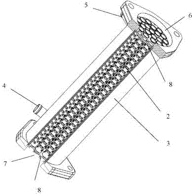
[0032] A heat exchanger, comprising, the heat exchange tube manufactured by the present invention, the shell, the water inlet pipe, the drain pipe, the air inlet, the air outlet and two tail plates, the two ends of the shell are respectively provided with a water inlet and a water outlet, A circular through hole with a diameter equal to the diameter of the heat exchange tube is opened on the end plate, and the two ends of the heat exchange tube are respectively sealed and welded to the circular through holes at the same position of the two end plates, and the two end plates are respectively sealed and fixed on the inlet. At the air port and the air outlet, the water inlet pipe and the water outlet pipe respectively seal the water inlet and the water outlet welded on the shell.


PUM


Abstract

The invention provides a heat exchange tube, a manufacturing method of the heat exchange tube and a heat exchanger with the heat exchange tube. Arc-shaped grooves perpendicular to the length direction of the heat exchange tube are formed in the surface of the heat exchange tube, the arc-shaped grooves are distributed in a discontinuously staggered mode in the circumferential direction of the heat exchange tube, and the arc-shaped grooves are evenly distributed in the length direction of the heat exchange tube. The surface of the heat exchange tube is designed to be of the structure that the arc-shaped grooves are formed in the discontinuously staggered mode, and the heat exchange area of the heat exchange tube can be effectively increased through the structure. Meanwhile, through the structure that the arc-shaped grooves are formed in the discontinuously staggered mode, gas can generate turbulent flow with strong impacts between clearances of the discontinuously staggered arc-shaped grooves, the impact force of the turbulent flow to the inner wall of the heat exchange tube is enhanced, accumulation of carbon in the gas is effectively reduced, and generation of the accumulated carbon is controlled.

Description

technical field [0001] The invention relates to the technical field of heat exchange, in particular to a heat exchange tube, a manufacturing method thereof and a heat exchanger equipped with the heat exchange tube. Background technique [0002] The heat exchange tube is the core component of the heat exchanger, and the structural design of the heat exchange tube has a great influence on the heat exchange efficiency of the heat exchanger. At present, the heat exchange tubes sold in the market mainly include circular tubes with a smooth tube structure and circular tubes with a spiral structure. The circular tubes with a bare tube structure have poor heat exchange efficiency due to the fast passage of hot gas and the short contact time with the refrigerant. Due to the existence of the helical structure, the hot gas generates turbulent flow when passing through the heat exchange tube, which increases the residence time of the hot gas in the heat exchange tube and improves the he...

Claims


Application Information

Patent Timeline
IPC IPC(8): F28F1/10F28D7/00B21D15/04
Inventor 孙玉祥陈亮远佐藤入内岛
Owner WUXI TRS HEAT EXCHANGER CO LTD
Why Eureka
Try Eureka