Improved device for measuring air specific heat ratio through adopting vibration method

An improved technology of air specific heat capacity, which is applied in the field of measurement of physical constants, can solve problems affecting the accuracy of measurement, difficulty in realization, uncertainty, etc., and achieve the effects of reducing collision, reducing turbulence, and benefiting symmetry and uniformity

Inactive Publication Date: 2015-01-21
SICHUAN UNIV
View PDF4 Cites 1 Cited by
  • Summary
  • Abstract
  • Description
  • Claims
  • Application Information

AI Technical Summary

Problems solved by technology

[0006] (2) The non-equivalence of the force on the top and bottom of the small hole does not have the mechanical conditions of simple harmonic vibration: the thrust of steel ball A on the upper and lower ends of the small hole is different, and the thrust on the lower end of the small hole is different. The thrust of the gas is large, and the thrust on the upper end (the gas leaks from the small hole) is small. The airflow environment in which the steel ball A moves is abrupt. Both documents are skeptical about its principle; if there is no small hole , the steel ball A is subjected to the thrust produced by the pressure difference, and the steel ball A will always rise without vibrating. Although, in the document "Improvement of the experimental method for measuring the gas specific heat capacity ratio by vibration method", it is proposed to find the steel ball under the small hole The balance position of A will then produce a vibration with an amplitude of about 1cm. Due to the lack of external force, it is difficult to achieve only through the adjustment of the air flow. The reason is that the steel ball A will fall when the air flow is small, and the steel ball A will rise when the air flow is large. Then the steel ball A is stable, then after the steel ball A is stable, the airflow must be increased to promote its rise, and after a certain distance, it must immediately return to the appropriate airflow mentioned above, so that the thrust generated by the pressure difference is equal to the gravity. This step hard to accomplish;
The literature "Improvement of the Experimental Method for Measuring Gas Specific Heat Capacity Ratio by Vibration Method" also found rotation (called spin in the literature) and collision phenomena. During the vibration process of steel ball A, we found that its reflected light changed, and then we marked it with red The pen draws a cross on the surface of the steel ball A, and it is found that the cross of the steel ball A rotates during the vibration process, and the direction of rotation changes with different instruments and at different times. This result is presented to us by the tube wall or / And the surface of the steel ball A is not uniform, and the asymmetric flow of the airflow at the small hole causes the steel ball A to rotate under asymmetric force. We also found that the frequency of its rotation also shows differences in different instruments and at different times. In other words, the steel ball A is not in a laminar flow environment, but has a certain turbulent flow, its rotational kinetic energy will affect the accuracy of the measurement, and, due to the uncertainty of the rotation, it cannot be corrected quantitatively

Method used


Image

  • Improved device for measuring air specific heat ratio through adopting vibration method
  • Improved device for measuring air specific heat ratio through adopting vibration method
  • Improved device for measuring air specific heat ratio through adopting vibration method

Examples


Embodiment Construction

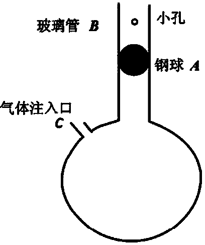
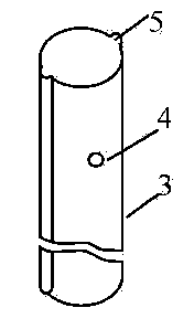
[0014] The same point as the prior art is that the parts of the device are the same, and all include a vibrating object and a glass tube 3, and a small hole 4 is arranged on the side of the glass tube 3.

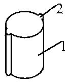
[0015] The steel ball in the prior art is replaced with a cylinder 1, and two or more ribs 2 are symmetrically distributed on the side of the cylinder 1, and the axes of all the ribs 2 are parallel to each other and the central axis of the cylinder 1, Preferably, 2-8 ribs 2 are blocked by the cylinder 1, and the distance between the cylinder 1 and the glass tube 3 is relatively small. Such a structure can effectively prevent the cylinder 1 from turning up and down.

[0016] Further, grooves 5 are set on the glass tube 3, and the number of grooves 5 corresponds to the number of ribs 2 on the side of the cylinder 1, that is, the number of grooves 5 is equal to the number of ribs 2 on the side of the cylinder 1. number, the rib 2 of the cylinder 1 slides up and down along the g...


PUM


Abstract

An improved device for measuring air specific heat ratio through adopting the vibration method relates to measurement of physical constants and aims to overcome problems existing in the conventional technology. The technical scheme is as follows: the improved device for measuring air specific heat ratio through adopting the vibration method comprises a glass tube and a vibration object, wherein the distance between the surface of the vibration object and the glass tube in the corresponding position can reach to 0.01-0.02 mm; small holes are formed in the side surface of the glass tube; the device is characterized in that the vibration object is improved from a steel ball to a cylinder; two or more protruding edges are symmetrically distributed on the side surface of the cylinder; all axes of the protruding edges are parallel to the central axis of the cylinder; grooves are formed in the glass tube; the number of the grooves is consistent with that of the protruding edges on the side surface of the cylinder; the cylinder can only be embedded into the glass tube grooves to slide upwards and downwards through the protruding edges; multiple circles and rows of the small holes are formed. The improved device has the benefits that the cylinder is prevented from rotating in the vertical direction; the protruding edges of the cylinder are matched with the grooves of the glass tube, so that rotation of the cylinder in the horizontal plane is avoided; owing to a larger gap between the cylinder and the glass tube, the flow manner of air is more close to laminar flow, so that collision between the steel ball and the wall of the glass tube is reduced.

Description

technical field [0001] The invention relates to the measurement of physical constants, and in particular provides a device for measuring air specific heat ratio by vibration method. Background technique [0002] Vibration method to measure specific heat capacity ratio of air is a commonly used method for measuring specific heat capacity ratio. The measurement method used in the physics laboratory, the experimental principle is detailed in "Improvement of the experimental method for measuring gas specific heat capacity ratio by vibration method", Journal of Taizhou University, December 2010 No. Volume 32, Issue 6, Page 39-42, "2 Experiments", and "Experimental Analysis of Air Specific Heat Capacity Ratio Measurement by Vibration Method, Laboratory Science, Volume 16, Issue 3, June 2013, Issue 35-37" "1.1 Principles of the original experiment". [0003] The principle adopted by the prior art, see figure 1 , the gas injection port injects gas continuously and stably, and the ...

Claims


Application Information

Patent Timeline
IPC IPC(8): G01N25/20
Inventor 胡再国邹旭敏罗明蓉雍志华饶大庆穆万军梁雅庭刘石丹何原于白茹田野中朱俊李伟
Owner SICHUAN UNIV
Why Eureka
Try Eureka