Side-mounted precision angular displacement self-detecting system

A detection system and angular displacement technology, used in general control systems, control/regulation systems, program control, etc., can solve the problems of not very high accuracy, can not achieve accurate measurement and measurement, and achieve small size and light weight. Effect

Active Publication Date: 2015-01-21
重庆大族时栅科技有限公司
View PDF5 Cites 3 Cited by
  • Summary
  • Abstract
  • Description
  • Claims
  • Application Information

AI Technical Summary

Problems solved by technology

[0004] At the same time, the inventor noticed that: (1) In the detected mechanical motion system, a considerable part has the characteristics of equal space division, such as gears (teeth), worm gears (teeth), bearings (balls), motors, etc. (groove), etc.; (2) The accuracy of this kind of equal division is not very high, called "mechanical equal division", which does not reach the level of "measurement equal division" required for precision measurement and control; (3) The total angular displacement sensor It is divided into a moving rotor part and a stationary stator part, which are respectively connected to the moving part and the stationary part of the machine under test. When the two move relative to each other, the sensor senses and outputs displacement information; (4) the existing known sensor In technology and measurement technology, some can achieve higher measurement accuracy with lower aliquot manufacturing accuracy, such as time grating displacement sensor

Method used


Image

  • Side-mounted precision angular displacement self-detecting system
  • Side-mounted precision angular displacement self-detecting system
  • Side-mounted precision angular displacement self-detecting system

Examples


Embodiment Construction

[0049] Design idea and specific structure of the present invention are further described in detail below in conjunction with accompanying drawing:

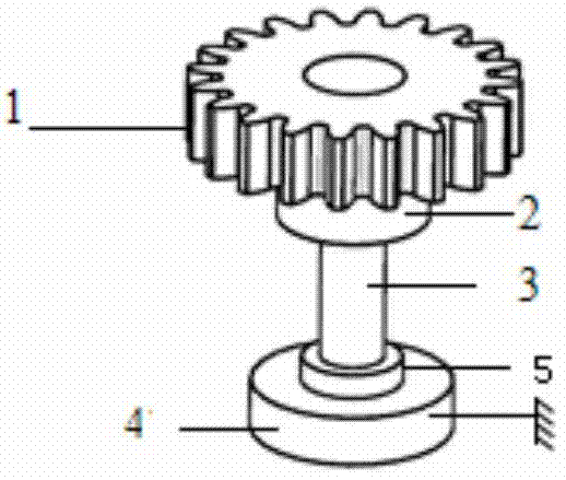
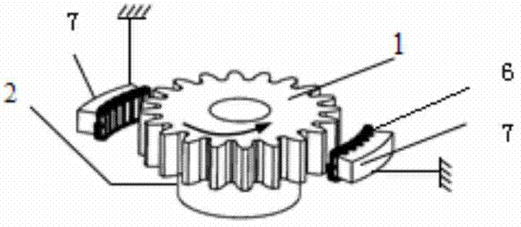
[0050]The invention proposes a system for automatically performing precise angular displacement detection and outputting the displacement information of the moving metal tooth-shaped body with the feature of mechanically dividing along the circumference. The invention adopts the principle of electromagnetic induction to make a group of electromagnetic induction probes including signal excitation coil, signal induction coil and signal compensation coil, and place one or more sets of the probes next to the moving metal body to be tested. Together with the microprocessor system, it can accurately obtain its movement displacement information in a non-contact manner. The excitation, induction and processing of the probe adopt some well-known electromagnetic sensor technologies, and one of the characteristics is that the probe adds equa...


PUM


Abstract

The invention provides a system enabling a moving metal toothed body with circumferentially and mechanically halving characteristics to automatically perform precision angular displacement detection and output displacement information. The side-mounted precision angular displacement self-detection system designs a group of detection heads which comprise exciting, induction and compensation coils, arranged beside a moving metal body to be detected and work with a microprocessor system to accurately obtain motion displacement information of the moving metal body in a non-contact mode. The system is characterized in that the detection heads are additionally provided with axially-halved grooves, and a single coil is axially wound and tangentially connected in series to weaken magnetic field edge effects of the coil; tooth crests of metal winding bases of the detection heads are tangentially and axially machined into a particular arc respectively; the metal body to be detected and toothed portions of the detection heads comply with set distribution principles; the detection heads are provided with signal compensation coils with independently adjustable compensation power supplies; the metal body to be detected and the detection heads are regarded as an overall mechanical system with a sensing function, and an online or system error correction technology is used, so that the whole system can have the capability of self-detection and precision displacement information output.

Description

technical field [0001] The invention belongs to the field of precision measurement of angular displacement. Background technique [0002] It is a long-standing major technical problem that traditional precision angular displacement sensors "cannot be installed" or "cannot be used normally after installation" on some mechanical systems in special and harsh environments. For example, super-large, strong vibration, hollow, mechanical equipment and weapon systems that work in harsh environments such as oil, dust, water vapor, etc. [0003] Traditional mechanical transmissions use various gears and worm gears to transmit power and position. At the same time, in order to ensure the accuracy of the movement, it is necessary to install an angular displacement sensor coaxially and concentrically with the measured gear 1 (that is, through the bearing 2 and the coupling 3), as shown in Figure 1 (a), 4 is the sensor stator, and 5 is the sensor rotor , if this sensor adopts the electro...

Claims


Application Information

Patent Timeline
Patent Type & Authority Applications(China)
IPC IPC(8): G05B19/18
CPCG05B19/40935
Inventor 彭东林武亮高中华孙世政汤其富陈锡侯范兵
Owner 重庆大族时栅科技有限公司
Why Eureka
Try Eureka