Wire winding device for rolling iron core transformer

A technology of winding device and transformer, applied in the direction of coil manufacturing, etc., can solve the problems of easy to produce core friction, easy softening of cardboard, long installation time, etc., to avoid damage to strength, fast assembly process, and long service life Effect

Active Publication Date: 2015-01-21
广东华力通变压器有限公司
View PDF6 Cites 3 Cited by
  • Summary
  • Abstract
  • Description
  • Claims
  • Application Information

AI Technical Summary

Problems solved by technology

[0003] The disadvantage of this winding method is that the requirements for installing the positioning device are relatively high, and the concentricity of the positioning devices at both ends must be ensured to be high, otherwise the iron core will be easily rubbed during winding, resulting in the failure to complete the winding, so the installation time is longer
The second disadvantage is that if cardboard is used as the inner support of the winding, the friction of the core column is also prone to occur during winding. If there is a problem during winding, it cannot be returned and rewound, and the entire coil must be rewound.
Moreover, in the relatively humid environment in the south, the cardboard is easy to soften, causing the gears to fail to rotate, which will also affect the winding of the coil, and even cause the entire coil to be scrapped.
Therefore, the production efficiency of this method is not high, and problems are prone to occur in the winding process and cause waste.

Method used


Image

  • Wire winding device for rolling iron core transformer
  • Wire winding device for rolling iron core transformer
  • Wire winding device for rolling iron core transformer

Examples


Embodiment Construction

[0034] In order to further facilitate those of ordinary skill in the art to better understand the essence of the present invention, the specific implementation manners of the present invention will be described in detail below in conjunction with the accompanying drawings.

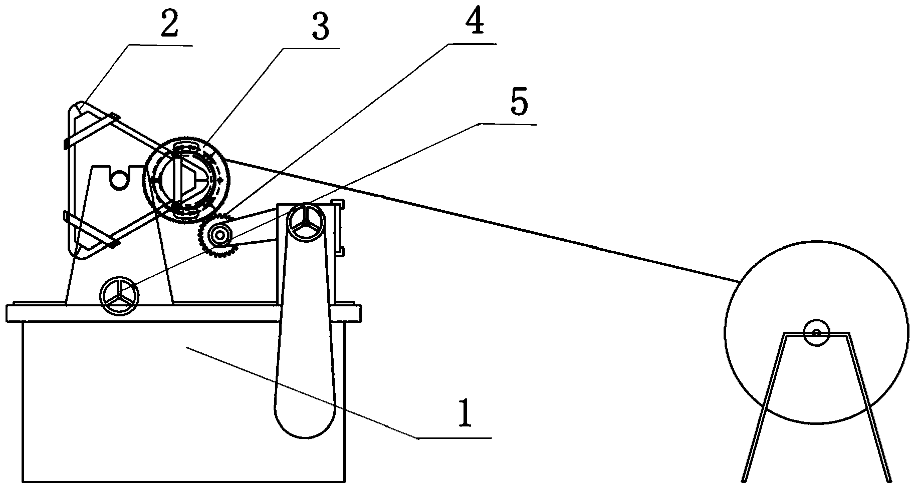
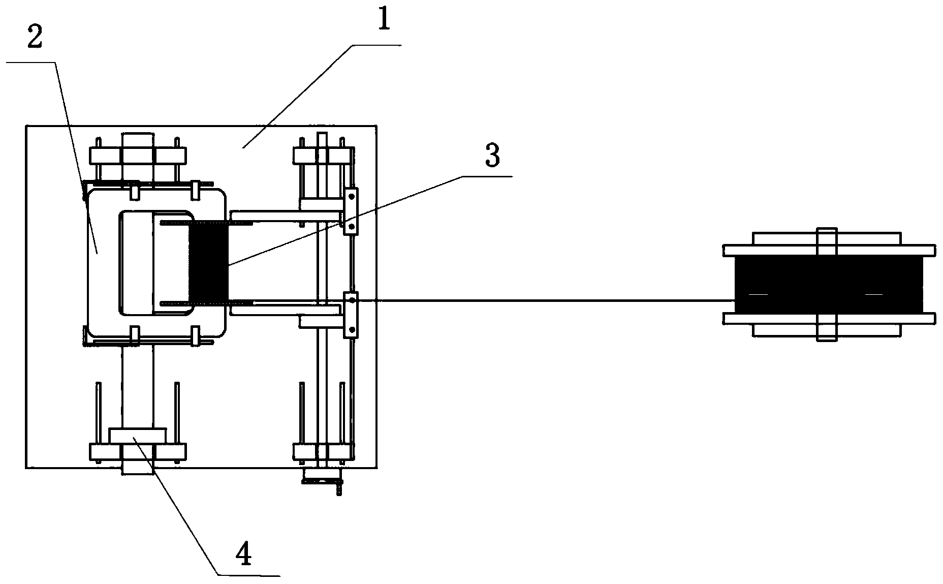
[0035] Such as Figure 1-Figure 2 As shown, a winding device for a wound core transformer includes: a frame 1 , an iron core 2 , a winding frame 3 , a driving gear 4 and a lifting device 5 .

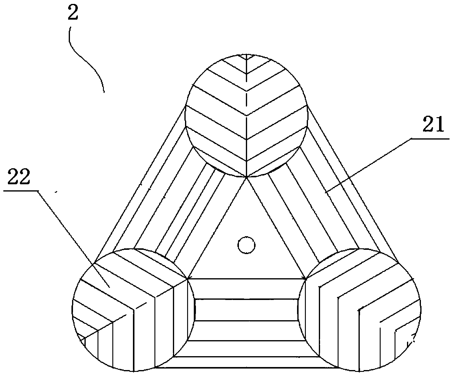
[0036] The iron core 2 is installed on the machine base 1 through a lifting device 5 , and a winding frame 3 is movable outside the iron core 2 , and driving gears 4 are respectively arranged at both ends of the winding frame 3 . The iron core 2 is connected with the lifting device 5 through a turning gear, and a turning motor connected with the turning gear is provided on the machine base 1 .

[0037] During actual work, the driving gear drives the winding frame to rotate, thereby realizing winding. When the windi...


PUM


Abstract

The invention discloses a wire winding device for a rolling iron core transformer. The wire winding device is characterized in that a machine base, an iron core, a wire winding frame, driving gears and a lifting device are included; the iron core is arranged on the machine base through the lifting device, the iron core is movably sleeved with the wire winding frame, and the driving gears are arranged at the two ends of the wire winding frame respectively; the iron core is connected with the lifting device through a turnover gear, and a turnover motor connected with the turnover gear is arranged on the machine base; the iron core is formed by splicing three single frames with the same geometric dimension, a core column is formed by side frames of every two adjacent single frames, and the whole iron core is of a triangular stereo structure formed by the three core columns. Compared with the prior art, the wire winding device has the advantages that the structure is simple, the device is convenient to assemble, and wire winding is fast.

Description

technical field [0001] The invention relates to the technical field of winding transformer preparation, in particular to a winding device for a wound core transformer. Background technique [0002] One of the key technologies of wound core transformers is how to conveniently and quickly wind coils on closed three-dimensional wound core transformers. The existing three-dimensional wound core transformer coil winding technology is to install a positioning device with a winding gear on the core column of the three-dimensional wound core, and then place cardboard or epoxy cloth board on the edge of the gear. [0003] The disadvantage of this winding method is that the installation of the positioning device is relatively high, and the concentricity of the positioning devices at both ends must be ensured to be high, otherwise the iron core will be easily rubbed during winding, resulting in the failure to complete the winding, so the installation time is longer. The second disadva...

Claims


Application Information

Patent Timeline
IPC IPC(8): H01F41/06
Inventor 欧伟洪
Owner 广东华力通变压器有限公司
Why Eureka
Try Eureka