
Method for restraining resonance mechanism low-frequency oscillation of power system

A low-frequency oscillation and power system technology, applied in the direction of reducing/preventing power oscillation, electrical components, circuit devices, etc., can solve the problems of poor damping effect of low-frequency oscillation of the resonance mechanism, failure to reach the damping level, etc., to ensure stability and increase The effect of system damping and suppression of low frequency oscillation

Active Publication Date: 2015-01-21
STATE GRID JIANGSU ECONOMIC RES INST +3
View PDF2 Cites 28 Cited by
  • Summary
  • Abstract
  • Description
  • Claims
  • Application Information

AI Technical Summary

Problems solved by technology

However, the additional damping control of the traditional unified power flow controller does not have a good damping effect on the low-frequency oscillation of the resonance mechanism. The reason is that the disturbance source of the low-frequency oscillation of the resonance mechanism continuously injects power disturbance into the system, and a high damping level is required to suppress it. However, the traditional method cannot reach the corresponding damping level

Method used


Image

  • Method for restraining resonance mechanism low-frequency oscillation of power system
  • Method for restraining resonance mechanism low-frequency oscillation of power system
  • Method for restraining resonance mechanism low-frequency oscillation of power system

Examples


Embodiment Construction

[0026] Below in conjunction with accompanying drawing and example the present invention will be further described.

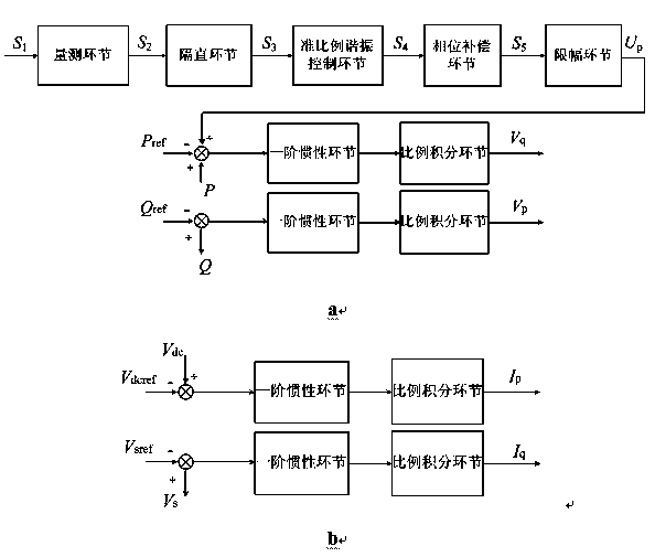
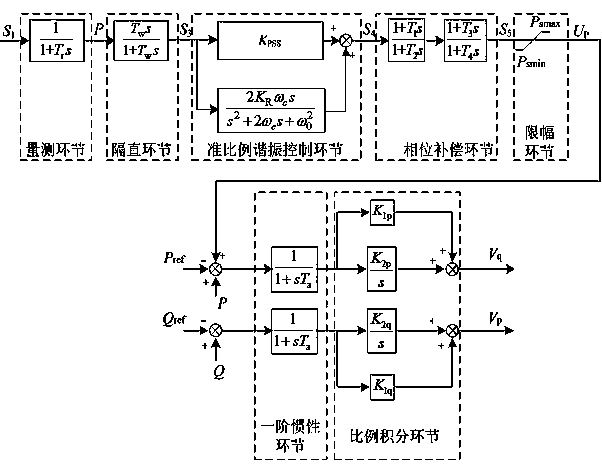
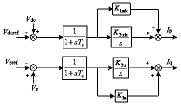
[0027] For electric devices including excitation generators, transformers, busbars, loads and other electrical components and a unified power flow controller, the present invention adopts such as figure 1 , 2 link processing and such as image 3 , 4 According to the transfer function (i.e. the controller) in each link, the output p-axis voltage V that has a great damping effect on the low-frequency oscillation of the resonance mechanism in the above system is obtained p , current I p and the output q-axis voltage V q , current I q , to achieve the suppression of the oscillation in the system, the specific process is as follows:

[0028] Step 1, using the measurement link to collect the oscillation signal S in the system 1 , signal S 1 The measurement transfer function through this link (i.e. the measurement controller) processing to obtain the measurem...


PUM


Abstract

The invention relates to a method for restraining resonance mechanism low-frequency oscillation of a power system. The method is applied to a unified power flow controller in the system and includes the steps that at the measurement step, signal collection is performed on the system, and a bus power signal P in signals is sequentially processed in the blocking step, the proportion resonance control step, the phase compensation step and the amplitude limiting step, so that an output control signal Up is obtained; the control signal and a reference value corresponding to the unified power flow controller are superposed, so that a corresponding adjusting signal is obtained; difference operation is performed on the signal P and the adjusting signal, difference operation is performed on the multiple obtained signals at the measurement step and corresponding reference values, all difference value signals are sequentially processed at the first-order inertia step and the proportional integral step, so that current and voltage corresponding to an output q axis and an output P axis are obtained and then injected into the system, and the damp for restraining the resonance mechanism low-frequency oscillation in the system is increased. The method has the advantages of being capable of effectively decreasing the resonance oscillation magnitude value and restraining the resonance mechanism low-frequency oscillation.

Description

technical field [0001] The invention relates to the field of power system control, in particular to a method for suppressing low-frequency oscillation of a resonance mechanism of a power system. Background technique [0002] Resonance mechanism Low-frequency oscillation is caused by the frequency of the external periodic power disturbance source being close to the inherent low-frequency oscillation frequency of the system. In recent years, due to the expansion of power system capacity and grid-connected scale, the power disturbance sources in the system have increased, and the low-frequency oscillation of the resonance mechanism has occurred from time to time, causing serious harm to the safe and stable operation of the power system. [0003] The emergence of flexible AC power transmission system (FACTS) provides a new effective means for suppressing the low-frequency oscillation of the resonance mechanism. The unified power flow controller (UPFC) is currently the most compr...

Claims


Application Information

Patent Timeline
IPC IPC(8): H02J3/24
CPCH02J3/241
Inventor 黄俊辉扬晓梅高正平蒋平冯双
Owner STATE GRID JIANGSU ECONOMIC RES INST
Learn More