Motor stator

A motor stator and frame technology, applied in the direction of electrical components, electromechanical devices, electric components, etc., can solve the problems of inability to accurately control the exact position, low utilization rate of frame winding, contact between enameled wire and iron core, etc., to reduce enameled wire damage, The effect of saving installation process and increasing the amount of winding

Inactive Publication Date: 2015-01-21
ZHEJIANG ZOBOW MECHANICAL & ELECTRICAL TECH
View PDF5 Cites 4 Cited by
  • Summary
  • Abstract
  • Description
  • Claims
  • Application Information

AI Technical Summary

Problems solved by technology

[0004] 1. The skeleton is divided into two parts, the left half and the right half, which are inserted and installed inside the iron core. Since the thickness of the left half and the right half is thicker, the winding amount of this part will be less than that of other parts. , the utilization rate of the bobbin winding of the same size is low, and the power will be smaller
[0005] 2. When the left half and right half of the skeleton are installed and combined, there will be certain errors during installation. There will be a certain gap between the left half and the right half of the skeleton, which will easily cause contact between the enameled wire and the iron core in the gap. If the enameled wire is damaged, Then it will cause the phenomenon of motor breakdown and so on.
[0006] 3. The skeleton is formed separately from the left half and the right half, and then assembled together in the iron core at the same time. The installation is more complicated, and it is impossible to accurately control the exact position of the left half and the right half relative to the iron core, which will easily cause assembly failure and reduce the product quality. Pass rate
[0007] 4. The edge of the frame is closed. When threading, it needs to be wound on the frame from above the edge of the frame to interfere with the winding process; after winding, the lead wire of the enameled wire is wound around the bottom of the frame. It is easy to cause damage to the enameled wire, and the damaged enameled wire contacts the iron core, causing motor breakdown and other phenomena.

Method used


Image

  • Motor stator
  • Motor stator
  • Motor stator

Examples


Embodiment Construction

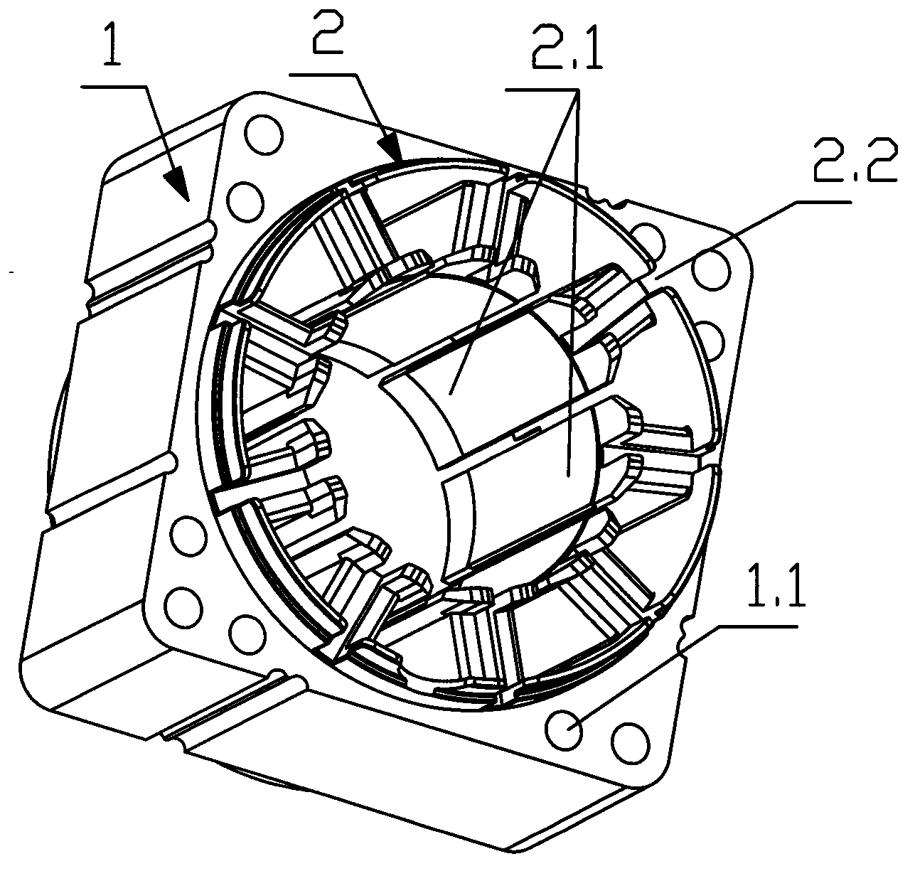
[0022] figure 1 It is a three-dimensional schematic view seen from the front side of the skeleton of the present invention, figure 1 The coil is not shown in. in figure 1 , The connecting lines between different components indicate that they have a connection relationship or a corresponding relationship between mounting holes.

[0023] Such as figure 1 As shown, a motor stator of the present invention includes an iron core 1, a coil, and a skeleton 2. The iron core 1 has a perforation in the center. The iron core 1 has a variety of molding methods. This embodiment uses the most common method at present, namely The iron core 1 is formed by successively stacking and pressing a plurality of silicon steel sheets, each silicon steel sheet is provided with a through hole in the center, and the multiple silicon steel sheets are superimposed to form a perforation of the iron core 1. The above structure is the same as most stator structures in the prior art, which can be clearly understoo...


PUM


Abstract

The invention discloses a motor stator which comprises an iron core, a coil and a framework, wherein a through hole is formed in the center of the iron core, and a plurality of wire slot bodies convenient to wind the coil are formed in the inner wall of the framework. The motor stator is characterized in that the framework is subjected to integral injection molding and is molded in the through hole of the iron core. A plurality of threading grooves convenient for threading are formed in the edge of the obverse side of the framework, and a wiring slot used for containing a coil leading-out wire is formed in the reverse side of the framework. The framework of the stator is integrally molded, so that the motor stator is simple in structure and saves mounting process. The motor stator has the advantages of improving the motor performance and reducing damage of enameled wires during operation. The motor stator belongs to the technical field of motors.

Description

Technical field [0001] The invention belongs to the field of motor technology, and more specifically, it relates to a motor stator. Background technique [0002] The stator is the stationary part of the motor. The stator consists of three parts: a stator core, a stator winding and a base. The main function of the stator is to generate a rotating magnetic field, while the main function of the rotor is to be cut by the lines of magnetic force in the rotating magnetic field to generate (output) current. [0003] The stator is usually mainly composed of iron core, coil, skeleton and so on. The current stator structure has the following defects: [0004] 1. The frame is divided into two parts, the left half and the right half, which are inserted into the core and installed in the core. Because the thickness of the left half and the right half is thicker, the winding amount of this part will be less compared with other parts. , The winding utilization rate of the same size skeleton is ...

Claims


Application Information

Patent Timeline
Patent Type & Authority Applications(China)
IPC IPC(8): H02K1/16
CPCH02K1/16H02K1/165H02K3/50
Inventor 李明武谢志明周波
Owner ZHEJIANG ZOBOW MECHANICAL & ELECTRICAL TECH
Why Eureka
Try Eureka