Installation structure of motor magnetic ring and motor

A technology of installation structure and magnetic ring, applied in the direction of magnetic circuit shape/style/structure, magnetic circuit rotating parts, etc., can solve the problems of unfavorable automatic production of stator components, low installation flexibility of Hall elements, and complex shaft processing process , to achieve the effect of facilitating automated production, ensuring service life and improving the degree of automated production

Active Publication Date: 2015-01-21
GUANGDONG WELLING ELECTRIC MACHINE MFG
View PDF5 Cites 4 Cited by
  • Summary
  • Abstract
  • Description
  • Claims
  • Application Information

AI Technical Summary

Problems solved by technology

[0006] The purpose of the present invention is to overcome the above-mentioned deficiencies in the prior art, and provide a motor magnetic ring installation structure and a motor with the installation structure, which aims to solve the problem of flexible installation of the Hall element caused by the direct installation of the magnetic ring on the rotating shaft of the existing motor Low precision, unfavorable to the automatic production of stator components and complex processing of the shaft or the technical problems of short service life of bearings

Method used


Image

  • Installation structure of motor magnetic ring and motor
  • Installation structure of motor magnetic ring and motor
  • Installation structure of motor magnetic ring and motor

Examples


Embodiment 1

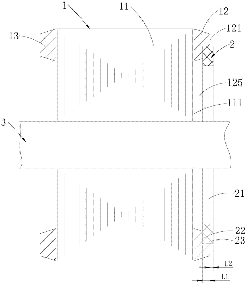
[0027] Such as Figure 1~3 As shown, the installation structure of the magnetic ring of the motor provided by Embodiment 1 of the present invention includes a squirrel-cage rotor 1 and a magnetic ring 2, and the squirrel-cage rotor 1 includes a rotor core 11 and a first end ring 12 disposed at one end of the rotor core 11 , the first end ring 12 has a first axial end face 121 facing away from the rotor core 11, a receiving groove 122 is recessed on the first axial end face 121 toward the side where the sub-core is located, and the magnetic ring 2 is fixed in the receiving Inside the slot 122. In this embodiment, the magnetic ring 2 is installed in the accommodating groove 122 of the squirrel cage rotor 1. On the one hand, it can effectively reduce the axial space occupied by the magnetic ring 2 inside the motor, and add other components to the stator winding (not shown). Parts that are convenient for automated production provide opportunities to facilitate the automated produ...

Embodiment 2

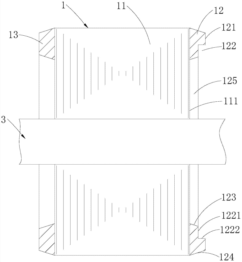
[0042] Such as Figure 4 and Figure 5 As shown, in the installation structure of the motor magnetic ring 2 provided in this embodiment, the rotor core 11 has a contact end surface 111 in contact with the first end ring 12, and the first end ring 12 has an inner ring wall 123 and an outer ring wall 124. The inner cavity 125 is enclosed by the ring wall 123 and the contact end surface 111 , and the accommodating groove 122 is disposed between the inner ring wall 123 and the outer ring wall 124 . The accommodating groove 122 is annular, and the cross-section of the one-side profile inside the accommodating groove 122 (the internal profile located on one side of the inner cavity 125) is roughly U-shaped, which consists of the bottom groove wall 1221 and the outside of the first end ring 12. The first side groove wall 1222 of the ring wall 124 is surrounded by the second side groove wall 1223 close to the inner ring wall 123 of the first end ring 12 . After the magnetic ring 2 i...


PUM


Abstract

The invention is applicable to the field of motors, and discloses an installation structure of a motor magnetic ring and a motor provided with the installation structure. The installation structure of the motor magnetic ring comprises a squirrel-cage rotor and a magnetic ring, wherein the squirrel-cage rotor comprises a rotor core and a first end ring arranged at one end of the rotor core, the first end ring is provided with a first axial end face back to the rotor core, the first axial end face is provided with an accommodating groove in a concave mode, and the magnetic ring is fixed in the accommodating groove. The installation structure disclosed by the invention reduces the axial space occupied by the magnetic ring inside the motor on the one hand, thereby providing a chance for additionally arranging parts convenient for automatic production on a stator winding, and being conducive to automatic production of an stator assembly; a Hall element is enabled to be placed in the motor horizontally or vertically on the other hand, thereby improving the installation flexibility of the Hall element; and on another aspect, a phenomenon that the machining process of a rotating shaft is caused to be complicated because the magnetic ring is fixed by processing edges on the rotating shaft and a phenomenon that the service life of a bearing is caused to be short because the magnetic ring is fixed by adding glue on the rotating shaft are avoided.

Description

technical field [0001] The invention belongs to the field of motors, in particular to a mounting structure of a magnetic ring of a motor and a motor with the mounting structure. Background technique [0002] Such as Figure 6 As shown, in the existing motor with the magnetic ring 2', the magnetic ring 2' is generally installed separately from the rotor 1' at different shaft sections of the rotating shaft 3', that is, the magnetic ring 2' is directly installed on the rotating shaft 3' After the magnetic ring 2' is installed on the rotating shaft 3', it generally needs to be axially positioned through the split retaining ring 4'. The mounting structure of the existing magnetic ring 2' has the following deficiencies in specific applications: [0003] 1) The magnetic ring 2' is directly installed on the rotating shaft 3', which occupies a large axial space inside the motor, so that the Hall sensing surface of the Hall element 6' can only be set in the radial direction; while th...

Claims


Application Information

Patent Timeline
Patent Type & Authority Applications(China)
IPC IPC(8): H02K1/22
Inventor 范文张守军井赟方强
Owner GUANGDONG WELLING ELECTRIC MACHINE MFG
Why Eureka
Try Eureka