Stirring device applicable to liquid medicine and chemical feed liquid

A stirring device and chemical technology, which is applied to mixers with rotating stirring devices, mixer accessories, chemical instruments and methods, etc., can solve the problems of cumbersome process and increase the burden on operators, and achieve simple operation and improved service life Effect

Active Publication Date: 2015-01-28
珠海君瑞恒医药科技有限公司
View PDF6 Cites 17 Cited by
  • Summary
  • Abstract
  • Description
  • Claims
  • Application Information

AI Technical Summary

Problems solved by technology

[0004] The above-mentioned feed liquid stirring device drives the stirring shaft by the motor to fully stir the feed liquid. After the feed liquid is stirred, it is necessary to manually open the shut-off valve to release the stirred feed liquid. This process is cumbersome and at the same time The operator must be on site to complete the process of discharging liquid, which increases the burden on the operator

Method used


Image

  • Stirring device applicable to liquid medicine and chemical feed liquid
  • Stirring device applicable to liquid medicine and chemical feed liquid
  • Stirring device applicable to liquid medicine and chemical feed liquid

Examples


Embodiment 1

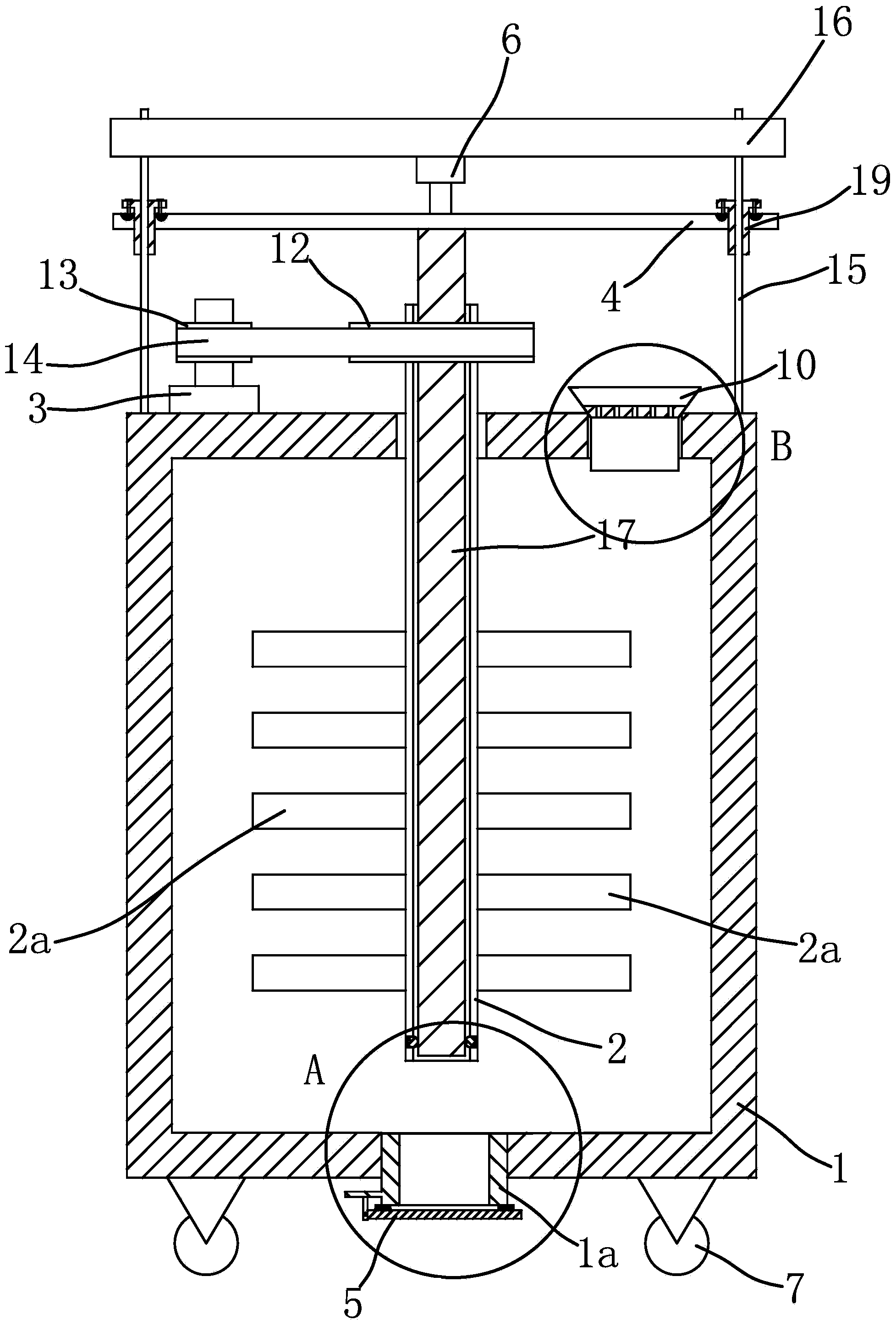
[0041] The stirring device suitable for liquid medicine and chemical material liquid is mainly used for stirring the material liquid. Such as figure 1 As shown, the stirring device suitable for liquid medicine and chemical feed liquid includes: a tank body 1, a stirring shaft 2, a motor 3, a guide plate 4, a cover plate 5, and an air cylinder 6.

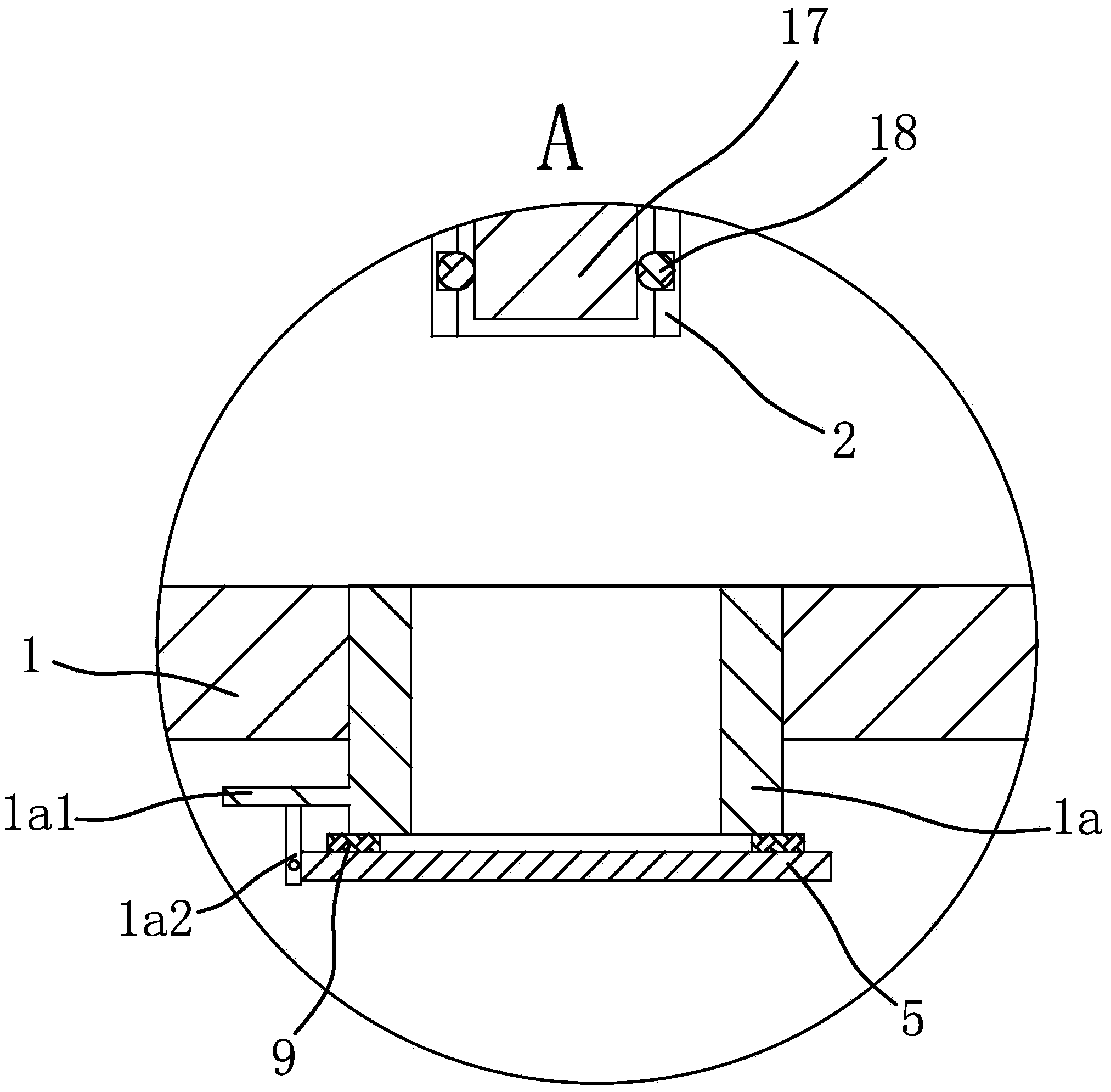
[0042] Wherein, the tank body 1 is a cuboid and has an inner cavity, and four rollers 7 are arranged at the bottom of the tank body 1 to facilitate the movement of the tank body 1 . The four rollers 7 are arranged symmetrically along the centerline of the tank body 1 , and the bottom of the tank body 1 has a liquid outlet pipe 1a communicating with the inner cavity thereof, and the liquid outlet pipe 1a is located at the center of the bottom of the tank body 1 . Further optimization, the liquid outlet pipe 1a and the tank body 1 are molded from the same material at one time, thereby improving the sealing performance of the connectio...

Embodiment 2

[0055] The structure and principle of this second embodiment are basically the same as that of the first embodiment. The difference is that the guide member is a guide rail and there are two guide rails. Both sides of the guide plate 4 have protruding sliders respectively, and the two sliders are respectively embedded in the corresponding rails. When the guide plate 4 reciprocates and translates under the action of the cylinder 6, the slider also translates up and down in the guide rail with the guide plate 4 and plays a better guiding effect, so that the ejector rod 17 can move down stably and make the cover plate 5 smoothly Rotate around the hinge point to open the liquid outlet pipe 1a, thereby further shortening the time it takes for the liquid outlet pipe 1a to turn from the sealed state to the open state.

Embodiment 3

[0057] The structure and principle of this third embodiment are basically the same as those of the first embodiment, except that the transmission mechanism includes a large gear and a small gear that mesh with each other, the large gear is connected with the output shaft of the motor 3, and the small gear is connected with the upper end of the stirring shaft 2 . The motor 3 drives the stirring shaft 2 to rotate through gear transmission, and has the advantage of stable transmission, so that the material liquid can be fully stirred.


PUM


Abstract

The invention provides a stirring device applicable to liquid medicines and chemical feed liquids and solves the problem of tedious operation of a conventional stirring device. The stirring device applicable to liquid medicine and chemical feed liquid comprises a stirring shaft and a tank body provided with a liquid inlet opening; the stirring shaft is vertically arranged in the tank body, and the upper end of the stirring shaft extends out of the tank body; a plurality of stirring paddles are arranged on the outer edge of the lower end of the stirring shaft; a liquid outlet pipe is arranged at the bottom of the tank body; a motor is arranged at the top of the tank body and drives the stirring shaft to rotate through a transmission mechanism; a joint pin is arranged on the outer edge of the liquid outlet pipe; a cover plate is hinged to the joint pin, and a torsional spring having the tendency of enable the cover plate to seal the liquid outlet pipe is arranged between the joint pin and the cover plate; the stirring shaft is hollow, and a mandril is inserted in the stirring shaft; an air cylinder which can enable the lower end of the mandril to be propped against the cover plate and enable the cover plate to overcome the torsion of the torsional spring and to rotate around the hinge point is arranged at the top of the tank body; the piston rod of the air cylinder is connected with the upper end of the mandril. The stirring device applicable to liquid medicine and chemical feed liquid has the advantages that the operation is simple and time is saved.

Description

technical field [0001] The invention relates to a liquid stirring device, in particular to a stirring device suitable for medicinal liquid and chemical material liquid. Background technique [0002] In the pharmaceutical and chemical industries, it is necessary to stir the material liquid, especially in the chemical industry, the chemical raw materials, such as the deployment of paint, need to be fully stirred. At present, most of the paint liquids are prepared manually. Basically, it is stirred with a wooden stick in a container with an open upper end. This stirring method has the problems of uneven stirring and large color difference of the prepared paint liquid. Odor has a greater impact on the health of operators. [0003] For the above problems, people have realized the shortcomings and made improvements, such as a paint stirring device disclosed in the Chinese patent library [application number: 201410369005.1; application publication number: CN 104084075A], which inc...

Claims


Application Information

Patent Timeline
Patent Type & Authority Applications(China)
IPC IPC(8): B01F7/18B01F15/02
Inventor 杜群芳
Owner 珠海君瑞恒医药科技有限公司
Why Eureka
Try Eureka