Rotary magnetorheological finishing wheel device

A magneto-rheological polishing and grinding wheel technology, which is applied in the field of ultra-smooth processing of the surface of optical parts, can solve problems such as difficult to increase shear force, achieve the effect of large-area polishing and improve processing efficiency

Inactive Publication Date: 2015-01-28
白素华
View PDF8 Cites 7 Cited by
  • Summary
  • Abstract
  • Description
  • Claims
  • Application Information

AI Technical Summary

Problems solved by technology

[0005] The above-mentioned magnetorheological polishing grinding head devices can realize the surface polishing of the workpiece, which has a certain novelty, but a key problem has been ignored in these technologies. The key to realizing magnetorheological polishing is to form a shear force. Larger, the higher the polishing efficiency, the existing technology relies on increasing the strength of the magnetic field and increasing the relative speed to achieve, the increase in the relative speed can increase the shear force, but only part of the shear force plays a role in polishing, because These technologies use a continuous magnetic pole structure. When the shear force is greater than the friction between the magnetorheological fluid and the grinding wheel, the magnetorheological fluid will slide along the direction of the magnetic field distribution. Therefore, the existing magnetorheological polishing process shears The magnitude of the force is actually limited by the friction between the magnetorheological fluid and the poles
To increase the shear force, the friction force must be increased. The common method is to increase the magnetic field strength, that is, to increase the attractive force between the magnetorheological fluid and the magnetic pole. Generally, the friction force is approximately equal to the attractive force multiplied by the friction coefficient. The coefficient of friction must be less than or equal to 1, generally less than 0.5 in practical applications, so it is difficult to increase the effective shear force by increasing the strength of the magnetic field

Method used


Image

  • Rotary magnetorheological finishing wheel device
  • Rotary magnetorheological finishing wheel device
  • Rotary magnetorheological finishing wheel device

Examples


Embodiment Construction

[0023] The present invention will be further described below in conjunction with accompanying drawing and specific embodiment:

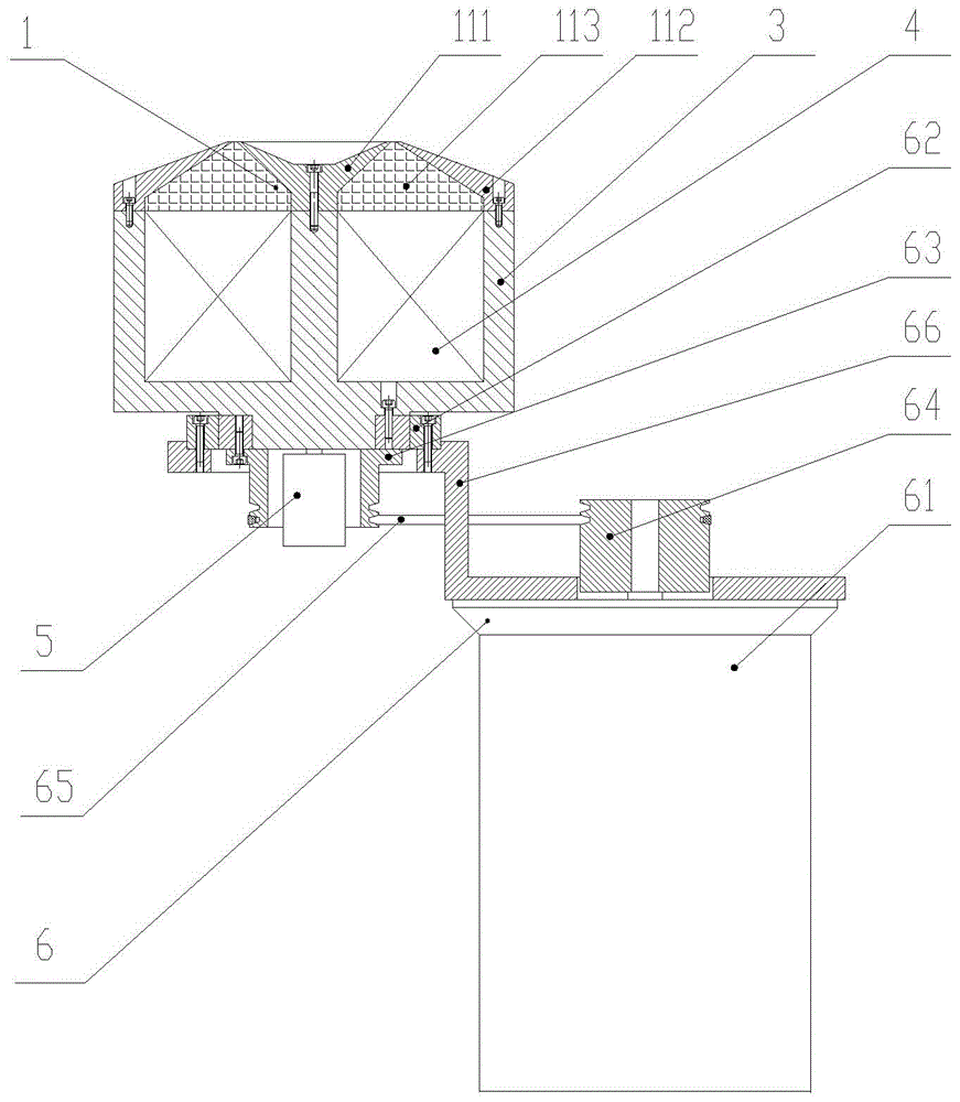
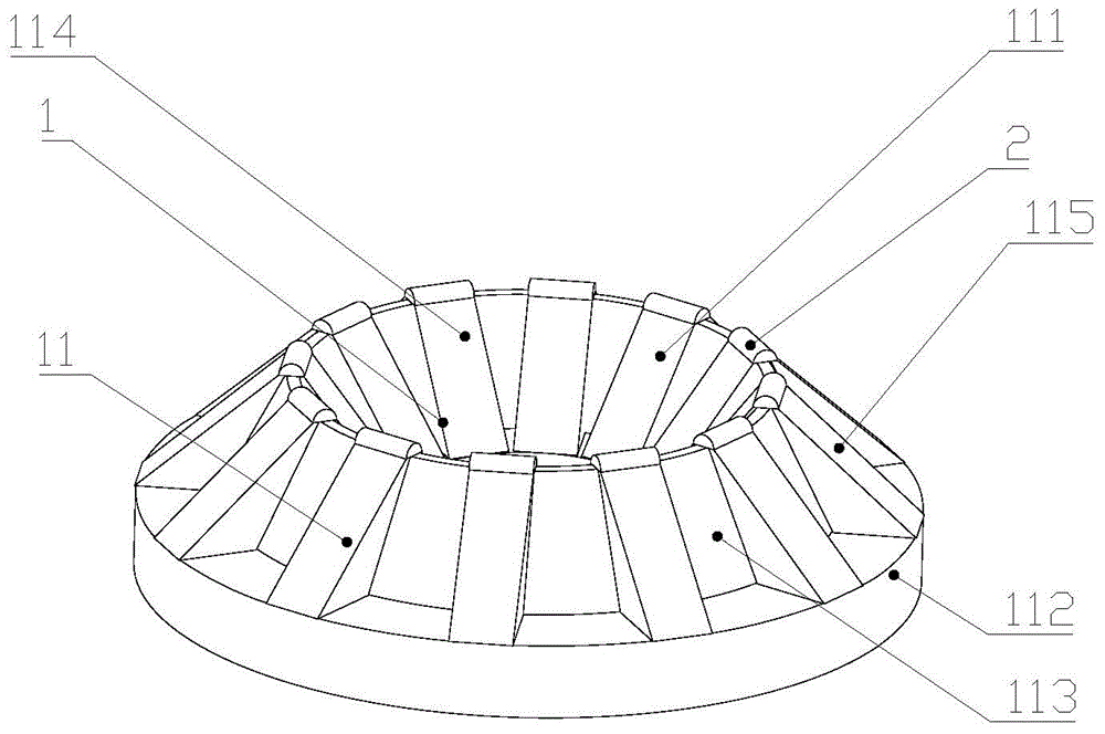
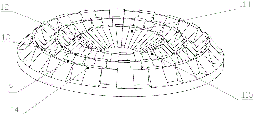
[0024] Such as figure 1 As shown, the rotary magneto-rheological polishing grinding wheel device of the present invention mainly includes a grinding wheel 1, a magnetic core 3, a coil 4, a magnetic brush 5, and a driving mechanism 6. Preferably, the magnetic core 3 is a W-shaped magnetic core. The grinding wheel 1 is fixed on the magnetic core 3 to ensure that the magnetic poles and the magnetic core 3 can be in contact, the coil 4 is wound on the magnetic core 3, and the magnetic brush 5 supplies power to the coil 4 to make the magnetic poles generate a magnetic field. The driving mechanism 6 includes a motor 61 , a bearing 62 , a pulley I 63 , a pulley II 64 , a belt 65 and a base 66 . The magnetic core 3 is fixed on the inner ring of the bearing 62, the inner ring of the bearing 62 is fixedly connected with the pulley I63, the outer ring of the b...


PUM


Abstract

The invention relates to a rotary magnetorheological finishing wheel device mainly comprising a grinding wheel, a magnetic core, a coil, a magnetic brush and a drive mechanism. The grinding wheel comprises at least one magnetic pole structure; each magnetic pole structure comprises an inner magnetic pole which is circular, an outer magnetic pole which is circular, and non-permeable filler arranged between the inner magnetic pole and the outer magnetic pole to separate them. Each inner magnetic pole is peripherally divided into multiple inner magnetic pole blocks arranged at intervals. The outer magnetic pole is peripherally divided into multiple outer magnetic pole blocks arranged at intervals. The inner magnetic pole blocks are in one-to-one correspondence with the outer magnetic pole blocks. In overview, the uppermost of each inner magnetic pole block and that of the corresponding outer magnetic pole block have a shortest distance. When the magnetic pole structures are electrified and generate a magnetic field, magnetorheological fluid is magnetized into interrupted Bingham bodies. By means of the feature that the magnetorheological fluid partially gathers towards the strong magnetic field, machining efficiency is greatly improved; by the use of array arrangement of the multiple magnetic pole structures, large-area finishing can be achieved.

Description

technical field [0001] The invention relates to the technical field of ultra-smooth processing on the surface of optical parts, in particular to a rotating magnetorheological polishing grinding wheel device. Background technique [0002] Magneto-rheological polishing technology uses the rheology of magnetorheological fluid in a magnetic field to polish, that is, under the action of a strong magnetic field, a viscoplastic flexible grinding wheel is formed by rheology in a gradient magnetic field, which behaves like a solid , The phenomenon that its flow characteristics are restored when the magnetic field is removed. The polishing of the part surface by this technology requires relative movement between the part and the grinding wheel. After adding the polishing liquid, a shear force will be formed to achieve the purpose of removal and high-quality polishing of the part surface. In the magnetorheological polishing process, the magnitude of the shear force determines the spee...

Claims


Application Information

Patent Timeline
Patent Type & Authority Applications(China)
IPC IPC(8): B24B1/00
CPCB24B1/005
Inventor 白素华
Owner 白素华
Why Eureka
Try Eureka