A film cutting machine

A slitter and film technology, applied in metal processing, packaging and other directions, can solve the problems of precision deviation, poor film quality, and low film efficiency.

Active Publication Date: 2016-09-21
深圳市泓普光电科技有限公司
View PDF9 Cites 0 Cited by
  • Summary
  • Abstract
  • Description
  • Claims
  • Application Information

AI Technical Summary

Problems solved by technology

[0003] The purpose of the present invention is to provide a film slitting machine to solve the problems of manual film application, stamping film application or rolling film application, precision deviation, low film application efficiency and poor film quality in the prior art.

Method used


Image

  • A film cutting machine
  • A film cutting machine
  • A film cutting machine

Examples


Embodiment Construction

[0024] The principles and features of the present invention are described below in conjunction with the accompanying drawings, and the examples given are only used to explain the present invention, and are not intended to limit the scope of the present invention.

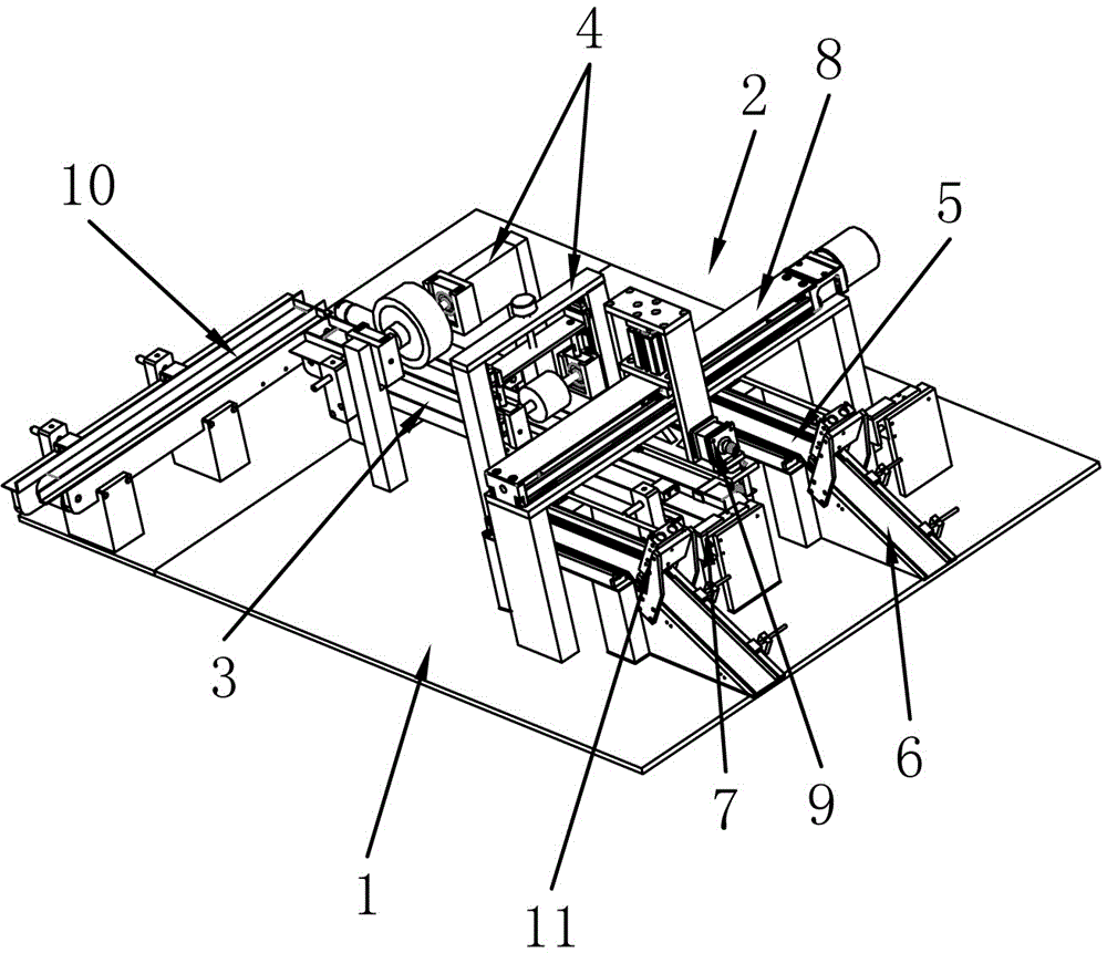
[0025] figure 1 It is a schematic structural view of the slitting equipment of the present invention; it includes a frame 1 and a slitting mechanism 2 arranged on the frame, the slitting mechanism includes a feeding guide rail 3, and a glue is provided between the beginning and the end of the feeding guide rail Assembly 4, the two sides of the end of the feeding guide rail are respectively provided with delivery slide rails 5, the end of the delivery slide rail is also provided with a finished slide rail 6, and there is a gap between the end of the delivery slide rail and the finished slide rail , the split cutter assembly 7 is provided at the gap, and the transport assembly 8 is also provided above the transport sl...


PUM


Abstract

The invention relates to the field of LED (Light Emitting Diode) light emitting element processing equipment, in particular to a film-laminating and splitting machine. The film-laminating and splitting machine comprises a frame and a splitting mechanism, wherein the splitting mechanism is arranged on the frame, is used for laminating a film to a material and splitting the material, and comprises a material conveying guide rail which is used for conveying the material; an adhesive coating component for film lamination is arranged between the start end and the tail end of the material conveying guide rail; conveying sliding rails are arranged on two sides of the tail end of the material conveying guide rail respectively; a transporting component which is used for transporting the material to the conveying sliding rails is further arranged above the conveying sliding rails; an overturning piece which is used for overturning the material is arranged on the side, opposite to the material conveying guide rail, of the transporting component; a finished product sliding rail is further arranged at the tail end of each conveying sliding rail; a splitter component which is used for splitting the material is further arranged at the tail end of each conveying sliding rail. The whole process is automatically completed; an adhesive tape on an adhesive coating wheel needs to be replaced by a new adhesive tape only when being completely consumed, and finished products are stacked in a material falling box; the whole film-laminating and splitting process is automatically completed, the film-laminating and splitting efficiency is high, the adhesive coating effect is good, and the production efficiency is greatly improved.

Description

technical field [0001] The invention relates to the field of LED light-emitting element processing equipment, in particular to a film sticking and cutting machine. Background technique [0002] After the LED shell is processed, it needs to be filmed. In the prior art, manual filming, stamping film or rolling film is generally used, but the efficiency of manual filming is low, and the precision of filming will become worse with the concentration of workers' mental strength. Accuracy deviation occurs, which leads to the problem of defective products. Although the stamping film has high film precision and high bonding degree, its film lamination speed is slow, which will affect the overall efficiency of LED processing. Although the rolling film lamination is more efficient, but The quality of the film is poor, and the existing film laminating machines only have the function of film laminating, and cannot directly produce finished products. It is necessary to cut the LED shell a...

Claims


Application Information

Patent Timeline
Patent Type & Authority Patents(China)
IPC IPC(8): B26D9/00B65B33/02
Inventor 傅潍
Owner 深圳市泓普光电科技有限公司
Why Eureka
Try Eureka