Ship engine room ventilation assembly

A technology for engine rooms and ships, which is applied in hull ventilation/heating/cooling, ship components, ship construction, etc. It can solve problems that affect the sight and health and safety of construction workers, poor exhaust effect, and dust cannot be discharged quickly and effectively. To achieve the effect of ensuring normal operation and physical health and safety, reducing noise pollution and prolonging service life

Inactive Publication Date: 2015-01-28
广州红帆科技有限公司
View PDF9 Cites 17 Cited by
  • Summary
  • Abstract
  • Description
  • Claims
  • Application Information

AI Technical Summary

Problems solved by technology

[0002] During the manufacturing process of the ship, various operations in the engine room area are carried out alternately, and assembly, electric welding, gouging, and grinding are intersected together to generate a large amount of dust, toxic gas or smoke. The ventilation of the building is very poor, and it is impossible to effectively discharge various dust, toxic gases or smoke out of the cabin, which affects the sight and health of construction workers.
At present, in the shipbuilding process, in order to discharge the dust, toxic gas and smoke generated during the manufacturing process, the construction personnel install a fan at the tail shaft hole at the bottom of the engine room to transport fresh air from the outside to the inside of the ship, but this structure The air supply and exhaust methods cannot satisfy the ventilation in the shipbuilding process, because the internal structure of the ship is complex, usually the ship has multiple layers of engine rooms, and the layers of engine rooms are separated by laminates, etc. Due to the obstruction of the laminates, dust etc. cannot quickly and effectively exhaust the outside of the ship, especially the bilge, which has the worst exhaust effect and affects the sight and health of construction workers.

Method used


Image

  • Ship engine room ventilation assembly
  • Ship engine room ventilation assembly
  • Ship engine room ventilation assembly

Examples


Embodiment Construction

[0070] The technical solutions of the present invention will be further described below in conjunction with the accompanying drawings and through specific implementation methods.

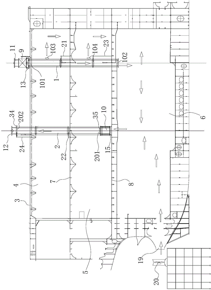
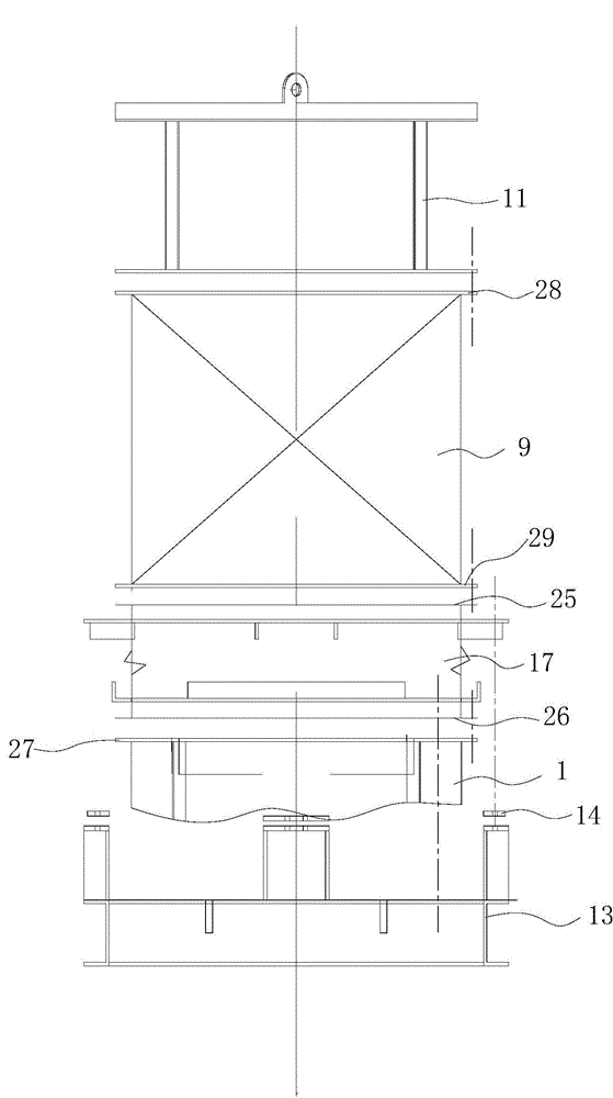
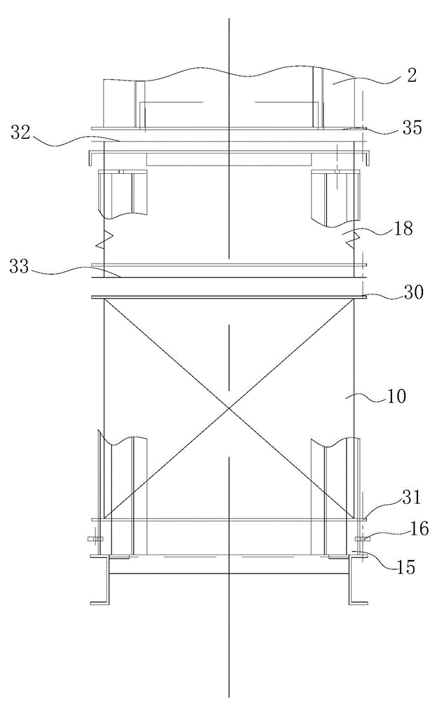
[0071] Such as Figures 1 to 5 As shown, a kind of marine engine room ventilation assembly of the present invention is mainly applied to ships with three-layer cabins. The deck 3 is set away from the side of the second cabin 5, and the first platform 7 is set between the first cabin 4 and the second cabin 5, so as to separate the first cabin 4 and the second cabin 5 by the first platform 7, and the second cabin 5 A second platform 8 is set between the bottom cabin 6 to separate the second engine room 5 and the bottom cabin 6 through the second platform 8 .

[0072] Among them, the ship engine room ventilation assembly includes an air supply pipe 1 and an air exhaust pipe 2. The air supply pipe 1 passes through the ship's deck 3, the first engine room 4, and the second engine room 5 in order to exte...


PUM


Abstract

The invention discloses a ship engine room ventilation assembly. The ship engine room ventilation assembly comprises an air supply pipe and an exhaust pipe, wherein the air supply pipe sequentially penetrates through a deck and an engine room of a ship to extend into a bottom compartment, the air supply pipe is provided with a first air inlet and a second air outlet, the first air inlet is arranged on the deck, the first air inlet is provided with an air blower, the first air outlet is arranged in the bottom compartment, and the air supply pipe is provided with an engine room air outlet in the engine room; the exhaust pipe penetrates through the deck to be arranged on one side, adjacent to the bottom compartment, of the engine room, the exhaust pipe is provided with a second air inlet and a second air outlet, the second air inlet is arranged in the engine room, the second air inlet is provided with an exhaust fan, the exhaust fan is fixed on the bottom of the engine room and communicated with the bottom compartment, and the second air outlet is arranged outside the deck. The ship engine room ventilation assembly can form an effective exhaust route, dust in the engine room can be rapidly and effectively discharged to the exterior of the engine room, and a good construction environment and the health of the construction personnel can be guaranteed.

Description

technical field [0001] The invention relates to the technical field of ship manufacturing, in particular to a ship engine room ventilation assembly. Background technique [0002] During the manufacturing process of the ship, various operations in the engine room area are carried out alternately, and assembly, electric welding, gouging, and grinding are intersected together to generate a large amount of dust, toxic gas or smoke. The ventilation of the cabin is very poor, and various dust, toxic gases or smoke cannot be effectively discharged out of the cabin, which affects the sight and health of construction workers. At present, in the shipbuilding process, in order to discharge the dust, toxic gas and smoke generated during the manufacturing process, the construction personnel install a fan at the tail shaft hole at the bottom of the engine room to transport fresh air from the outside to the inside of the ship, but this structure The air supply and exhaust methods cannot s...

Claims


Application Information

Patent Timeline
Patent Type & Authority Applications(China)
IPC IPC(8): B63J2/10B63J2/06
Inventor 刘文远张龙陈冠钦
Owner 广州红帆科技有限公司
Why Eureka
Try Eureka