Method for preventing dry dedusting system of semi-steel making converter from blowing and venting

A steelmaking converter and dry dust removal technology, applied in the direction of manufacturing converters, etc., can solve the problems of reducing the damage degree of dust collectors, equipment damage, explosion venting, etc., so as to reduce non-production operation time, prolong service life, and reduce explosion venting. the effect of the number of times

Active Publication Date: 2016-04-27
PANGANG GRP XICHANG STEEL & VANADIUM CO LTD
View PDF2 Cites 0 Cited by
  • Summary
  • Abstract
  • Description
  • Claims
  • Application Information

AI Technical Summary

Problems solved by technology

[0002] In the existing technology, the dry dust removal system is mainly used to purify and recover the flue gas generated by the semi-steel steelmaking converter. When the CO, O in the electric field of the dust collector 2 When the gas content reaches a certain proportion, it may cause an explosion. Therefore, the electrostatic precipitator (EP) is equipped with an explosion venting device. Once an explosion occurs in the dust collector, it can be automatically opened to discharge the burning and expanding gas in time and can be automatically reset to reduce The degree of damage of the dust collector ensures the long-term operation of the dust collector, but each explosion vent will also cause damage to the equipment, so how to prevent explosion venting becomes an important factor to prolong the life of the dry dust removal system
[0003] At present, only manufacturers using double-link technology use semi-steel smelting. Compared with molten iron smelting, semi-steel smelting is more prone to blowing and venting with dry dust removal system of converter. Therefore, semi-steel steelmakers using dry dust removal system need to Considering the difficulties of semi-steel making, you have to face the problem of "explosion venting" in the steelmaking process. The problem of blowing and venting is more serious when the amount of slag flowing from the converter is large or when scrap steel is added.

Method used


Image

  • Method for preventing dry dedusting system of semi-steel making converter from blowing and venting
  • Method for preventing dry dedusting system of semi-steel making converter from blowing and venting
  • Method for preventing dry dedusting system of semi-steel making converter from blowing and venting

Examples


example 1

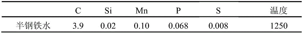
[0039] Semi-steel is smelted on a 180t converter in a steel plant. The semi-steel is molten steel obtained after desulfurization and vanadium-extracting molten iron containing vanadium. The composition and temperature of the semi-steel entering the furnace are shown in Table 1.

[0040] Table 1 Composition (%) and temperature (℃) of semi-steel into furnace

[0041]

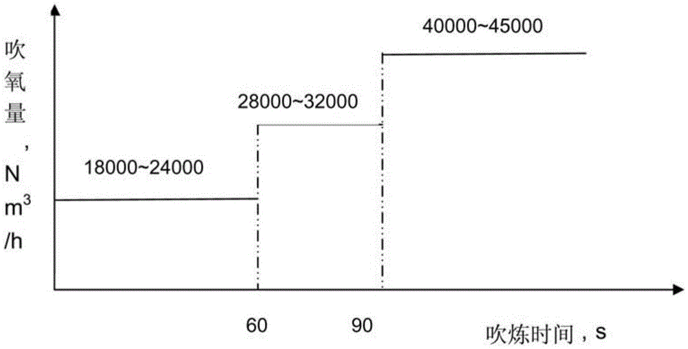
[0042] Among them, there is slag from the previous furnace in the converter, the iron mixing is completed and the blowing is ready to start, and within 0-60s of the converter blowing: adjust the oxygen blowing volume of the top blowing oxygen lance to 20000Nm 3 / h, the gun position of the top blowing oxygen lance is controlled to 2.0m, and the blowing is started; within 30s after the start of the blowing, 42Kg of carbon powder is added from the high-level silo of the converter.

[0043] During blowing 60~90s, control the oxygen blowing volume of the top blowing oxygen lance to 30000Nm 3 / h, the gun position of...

example 2

[0047] The semi-steel is smelted in a 200t converter in a steel factory. The semi-steel is molten steel obtained after desulfurization and vanadium extraction of vanadium-containing molten iron. The composition and temperature of the semi-steel entering the furnace are shown in Table 2.

[0048] Table 2 Composition (%) and temperature (℃) of semi-steel into furnace

[0049]

[0050] Among them, there is slag from the previous furnace in the converter, and the iron mixing is completed and the blowing is ready to start. Within 0 to 60 seconds of blowing: adjust the oxygen blowing volume of the top blowing oxygen lance to 18000Nm 3 / h, start blowing, the blowing gun position is controlled at 2.2m; within 15s after the start of blowing, add 80Kg of ferrosilicon from the high-level silo of the converter.

[0051] Within 60-90 seconds of blowing, control the oxygen blowing volume of the top blowing oxygen lance to 28000Nm 3 / h, the gun position of the top blowing oxygen lance is...

example 3

[0055] The semi-steel is smelted on a 250t converter in a steel factory. The semi-steel is molten steel obtained after desulfurization and dephosphorization of molten iron. The composition and temperature of the semi-steel entering the furnace are shown in Table 3.

[0056] Table 3 Composition (%) and temperature (℃) of semi-steel in the furnace

[0057]

[0058] Among them, 10t (supplementary amount of added scrap steel) steel scrap is added to the converter. When the iron mixing is completed and the blowing is ready to start, within 0-60 seconds of blowing: adjust the oxygen blowing amount of the top blowing oxygen lance to 23000Nm 3 / h, adjust the gun position to 2.2m to start blowing; within 15s after the start of blowing, add 50Kg of ferrosilicon (or aluminum shot) from the high-level silo of the converter. During blowing 60~90s, control the oxygen blowing volume of the top blowing oxygen lance to 34000Nm 3 / h, gun position control 1.5 ~ 1.6m; after blowing 90s, contr...


PUM


Abstract

The invention provides a method for preventing blowing explosion venting of a dry dust-removing system of a semi-steel steelmaking converter. The method comprises the following steps: adding semi-steel into a 180-260T steelmaking converter; after the beginning of blowing, within 60s, controlling the oxygen blowing amount to be 18000-24000Nm<3> / h and controlling the position of an oxygen lance at 2-2.4m; after blowing for 60-90s, controlling the oxygen blowing amount to be 28000-32000Nm<3> / h; after blowing for 90s, controlling the oxygen blowing amount to be 40000-45000Nm<3> / h; after the beginning of blowing, within 30s, adding a combustion accelerator into the converter and controlling the bottom blowing gas supplying amount to be 400-600NL / h; within 30-600s of blowing, reducing the bottom blowing gas supplying amount and controlling the bottom blowing gas supplying amount to be 300-500NL / h; after blowing for 600s, controlling the bottom blowing gas supplying amount to be 800-1200NL / h. By the method, in the smelting process of the converter, the dry dust-removing system can be protected from explosion venting.

Description

technical field [0001] The invention relates to the technical field of steelmaking, and more specifically relates to a method for reducing or preventing explosion venting of a dry dust removal system in the process of semi-steel making. Background technique [0002] In the existing technology, the dry dust removal system is mainly used to purify and recover the flue gas generated by the semi-steel steelmaking converter. When the CO, O in the electric field of the dust collector 2 When the gas content reaches a certain proportion, it may cause an explosion. Therefore, the electrostatic precipitator (EP) is equipped with an explosion venting device. Once an explosion occurs in the dust collector, it can be automatically opened to discharge the burning and expanding gas in time and can be automatically reset to reduce The degree of damage of the dust collector ensures the long-term operation of the dust collector, but each explosion vent will also cause damage to the equipment,...

Claims


Application Information

Patent Timeline
Patent Type & Authority Patents(China)
IPC IPC(8): C21C5/40
Inventor 张彦恒邓林喻林龚洪君
Owner PANGANG GRP XICHANG STEEL & VANADIUM CO LTD
Why Eureka
Try Eureka