
Optical lens used for LED (light-emitting diode) lamp and LED lamp

A technology of LED lamps and optical lenses, which is applied in the field of optics, can solve the problems that a single LED cannot meet the requirements of light distribution and distribution of lamps, cannot meet the needs of actual use, and the light-emitting angle of LED lamps is small, and achieve low assembly process requirements, The effect of high practical significance and simple structure

Inactive Publication Date: 2015-01-28
SHANGHAI NANHUA ELECTRONICS
View PDF0 Cites 0 Cited by
  • Summary
  • Abstract
  • Description
  • Claims
  • Application Information

AI Technical Summary

Problems solved by technology

However, due to the Lambertian light emission characteristics of a single LED itself, it cannot meet the requirements of actual lighting for light distribution of lamps and lanterns. It is necessary to use lenses for secondary optical treatment on multiple LEDs to meet the use requirements.
At present, most of the lenses used in LED lamps are designed for secondary light distribution based on a single LED. The biggest defect of this method is that the light-emitting angle of LED lamps is small (less than 150 degrees), which cannot be compared with traditional incandescent lamps. Compared with the wide light distribution angle of energy-saving lamps, it cannot meet the needs of actual use

Method used


Image

  • Optical lens used for LED (light-emitting diode) lamp and LED lamp
  • Optical lens used for LED (light-emitting diode) lamp and LED lamp
  • Optical lens used for LED (light-emitting diode) lamp and LED lamp

Examples


Embodiment Construction

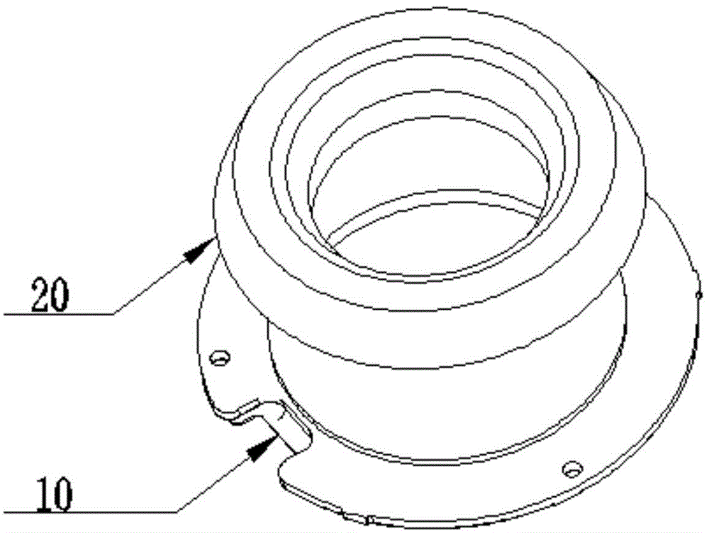
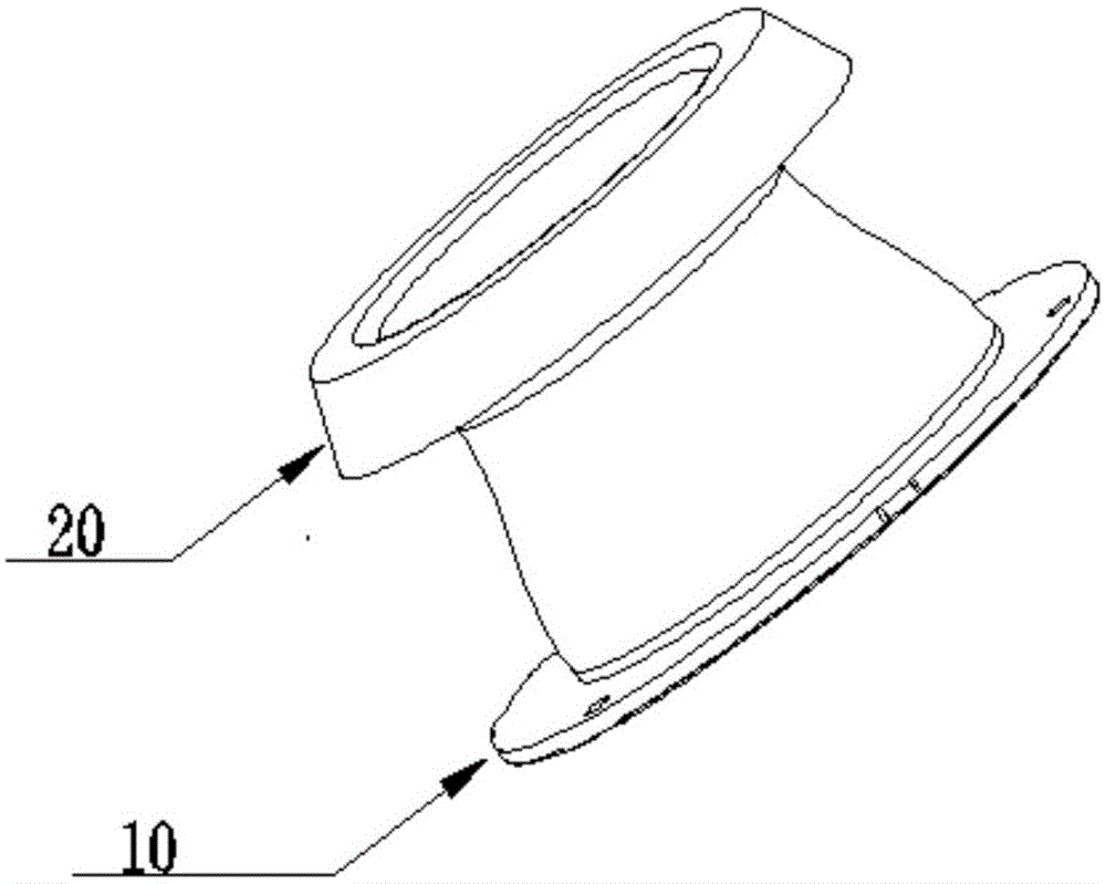
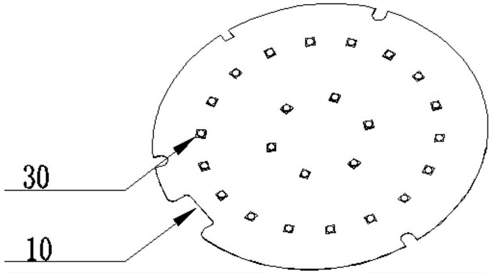
[0038] figure 1 with figure 2 A schematic structural diagram of an LED lamp according to a preferred embodiment of the present invention is shown, image 3 A schematic diagram of the structure of the light board, Figure 4 It is a top view of LED lamps. Figure 5 A cutaway view of the LED luminaire is given.

[0039] This embodiment provides an LED lamp, including an LED lamp bead 30 and an optical lens 20, the LED lamp bead 30 is fixed on the lamp board 10, and a plurality of LED lamp beads are arranged in the cavity of the optical lens 20, wherein the optical The lens 20 includes a light guide part 40 and a light emitting part 50. The light guide part 40 has a cavity for accommodating a plurality of LED lamp beads. The light guide part has a first surface 41 and a second surface 42 opposite to each other. The first surface 41 and the second surface The surface 42 can totally internally reflect and transmit the light emitted by the LED beads contained in the cavity to th...


PUM

PropertyMeasurementUnit
Roughaaaaaaaaaa

Abstract

The invention discloses an optical lens used for an LED (light-emitting diode) lamp and the LED lamp. The optical lens comprises a light guide part and a light-emitting part; the light guide part is provided with a cavity for containing multiple LED lamp beads; the light guide part is provided with a first surface and a second surface which are opposite; each of the first surface and the second surface is a fully reflecting surface capable of performing total internal reflection on light emitted from the LED lamp beads contained in the cavity to conduct the light to the light-emitting part; the light-emitting part is provided with a light-emitting face and emits the light conducted by the light guide part. Compared with the traditional optical lens, the optical lens provided by the invention has the characteristics that the light emitted from the LED lamp beads is conducted to the light-emitting part by the light guide part, and different optical requirements are met by changing the height of the light guide part and the curved surface structure of the light-emitting part; the structure is simple, and the assembly process requirement is low; the defect that the assembly precision requirement is high due to the fact that the traditional optical lens needs to meet the optical requirement is greatly overcome; the optical lens has a practical significance.

Description

technical field [0001] The invention relates to the field of optics, in particular to an optical lens for an LED lamp and the LED lamp. Background technique [0002] LED has superior characteristics such as long life, environmental protection and energy saving. At present, the use of LED as a lighting source has been vigorously promoted and applied. However, due to the Lambertian light emission characteristics of a single LED itself, it cannot meet the requirements of actual lighting for light distribution of lamps and lanterns. It is necessary to use lenses for secondary optical treatment on multiple LEDs to meet the requirements for use. At present, most of the lenses used in LED lamps are designed for secondary light distribution based on a single LED. The biggest defect of this method is that the light-emitting angle of LED lamps is small (less than 150 degrees), which cannot be compared with traditional incandescent lamps. Compared with the wide light distribution angl...

Claims


Application Information

Patent Timeline
IPC IPC(8): F21V5/04F21V8/00F21Y101/02
CPCF21K9/61F21V5/046F21V5/048F21Y2101/00F21Y2105/10F21Y2105/12
Inventor 肖飞张磊
Owner SHANGHAI NANHUA ELECTRONICS
Learn More