

Heat exchanger
A heat exchanger, one-to-one corresponding technology, applied in the direction of heat exchanger type, heat exchanger shell, indirect heat exchanger, etc., can solve the problem of long heat exchanger pipeline, poor cooling effect, heat exchanger pipeline and There are not many problems such as the contact area of the cooling medium, so as to achieve the effect of long cooling tube path, small occupied space and good cooling effect
- Summary
- Abstract
- Description
- Claims
- Application Information
AI Technical Summary
Problems solved by technology
Method used
Image

Examples
Embodiment Construction
[0013] The technical solutions of the present invention will be further described below in conjunction with the accompanying drawings and through specific implementation methods.
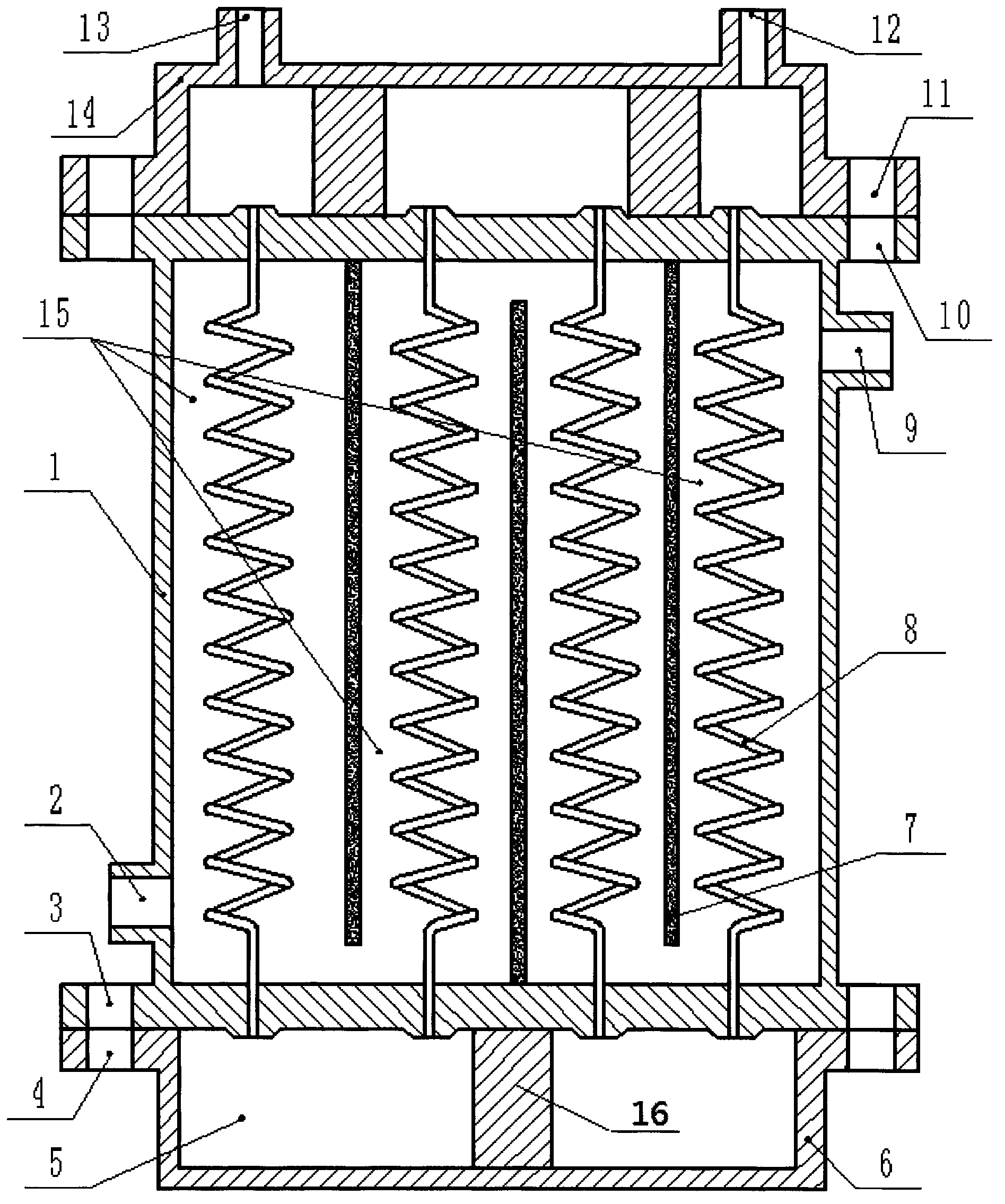
[0014] see Figure 1-2 , a heat exchanger, including a cooling tank 1, a longitudinal baffle 7 and an upper end cover 14; the cross-section of the cooling tank 1 is square, and four sets of tubes 8 are arranged horizontally and laterally in the cooling tank 1 , each group of tubes 8 is provided with at least two along the horizontal and vertical directions, and the tubes 8 are helical. The design of the helical tubes increases the pipeline stroke of the tubes 8 and improves the heat exchange effect. Wherein, each adjacent two groups A longitudinal baffle 7 is arranged between the tubes 8, the longitudinal baffle 7 on the left side is arranged between the first group of tubes 8 and the second group of tubes 8, and the middle longitudinal baffle 7 is arranged on the second group of tubes 8. Between t...
PUM
 Abstract
Description
Claims
Application Information