
Rapid measurement route planning method of sections of blades of aviation engine

An aero-engine, measurement path technology, applied in measurement devices, instruments, etc., can solve the problems of inability to realize real surface measurement, complex motion control, inability to take into account efficiency and accuracy, etc., to solve practical problems in factories, meet production needs, algorithms Simple and clear effect

Inactive Publication Date: 2015-01-28
XI AN JIAOTONG UNIV
View PDF5 Cites 14 Cited by
  • Summary
  • Abstract
  • Description
  • Claims
  • Application Information

AI Technical Summary

Problems solved by technology

These methods either cannot measure the real curved surface, or require complex motion control, or need to repeat the scanning section multiple times. In short, they cannot balance efficiency and accuracy.

Method used

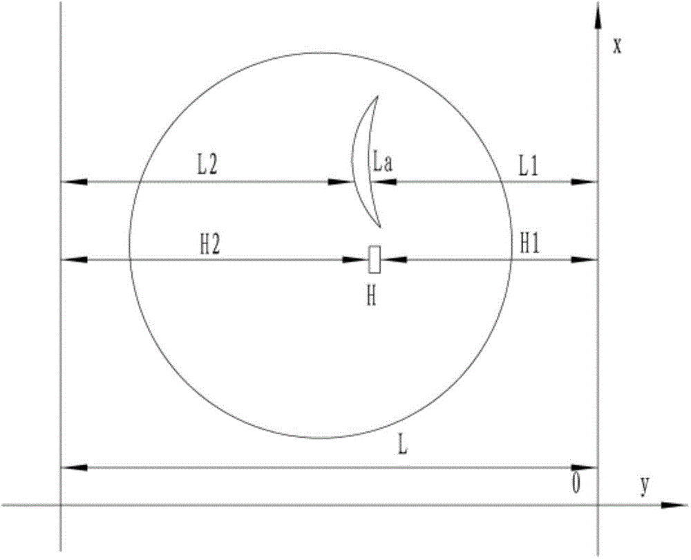

Image

  • Rapid measurement route planning method of sections of blades of aviation engine
  • Rapid measurement route planning method of sections of blades of aviation engine

Examples


Embodiment Construction

[0021] The present invention will be described in detail below in conjunction with the accompanying drawings.

[0022] A fast measurement path planning method for the section of an aeroengine blade, comprising the following steps:

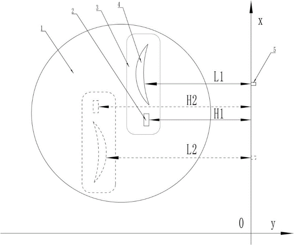
[0023] 1. Refer to the attached figure 1 , in the first step, the blade 4 to be tested is installed on the fixture 3, placed vertically on the horizontally rotatable measuring platform 1, and the standard gauge block 2 is installed on the fixture 3;

[0024] In the second step, when measuring, adjust the measuring sensor 5 clamped on the X-axis so that it can measure the distance H1 from the side of the standard gauge block 2 opposite to the X-axis, rotate the measuring platform 1180 degrees, and measure the standard gauge block 2 The distance H2 from the opposite side to the X axis, figure 1 The dotted line is the measurement state after rotating 180 degrees;

[0025] The third step is to adjust the measuring sensor 5 to the required characteri...


PUM


Abstract

Disclosed is a rapid measurement route planning method of sections of blades of an aviation engine. The blades to be measured are mounted on a clamp, a measuring transducer that is clamped on an X shaft is adjusted, then the measuring transducer is adjusted to required characteristic sections of the blades, the measuring transducer scans the characteristic sections of the blades along the X shaft, and a data sequence is collected; then a measuring table is rotated for 180 degrees so that other side edges of the blades are scanned to collect a data sequence; data of the characteristic sections of the blades that are scanned twice are converted in the same coordinate system through thickness of a known standard gauge block and conversion of coordinates, a characteristic section curvilinear equation is determined through a fitting function, and parameters of the characteristic sections of the blades are obtained; the measuring transducer is moved in a vertical direction to different positions so as to achieve measurement of the characteristic sections with different heights of the blades. According to the rapid measurement route planning method of the sections of the blades of the aviation engine, the movement control is simple, data collection speed is high, algorithms are simple and clear, and implementation in terms of engineering is easy.

Description

technical field [0001] The invention relates to the technical field of measuring the profile size of an aero-engine blade, in particular to a path planning method for rapid measurement of the cross-section of an aero-engine blade. Background technique [0002] Aeroengine blades are one of the core components of high-performance engines, and are often hailed as "the heart of the heart". Its processing and manufacturing is one of the key points and difficulties in engine manufacturing. The profile of the blade is generally a complex curved surface, the processing procedure is relatively complicated, and the processing is difficult. The quality of the profile has a decisive impact on the performance of the engine. At the same time, due to the large number, they have been in service for a long time under harsh working conditions, and the performance requirements are extremely high. Therefore, in the detection of engine components, the detection of blade profile is of great sign...

Claims


Application Information

Patent Timeline
Patent Type & Authority Applications(China)
IPC IPC(8): G01B21/20
CPCG01B21/20
Inventor 李兵孙彬陈磊李健魏翔刘丙才
Owner XI AN JIAOTONG UNIV
Learn More