Aerial intelligent robot used for radio monitoring

A radio monitoring and intelligent robot technology, applied in direction finders using radio waves, radio wave measurement systems, radio wave direction/deviation determination systems, etc., can solve the problems of large body, high manufacturing cost, and high technical requirements for operators , to achieve a high level of intelligence, avoid mutual calls, and reduce mutual interference.

Active Publication Date: 2015-01-28
XIHUA UNIV +1
View PDF7 Cites 8 Cited by
  • Summary
  • Abstract
  • Description
  • Claims
  • Application Information

AI Technical Summary

Problems solved by technology

Since the cost of each flight is more than hundreds of thousands of yuan, and it cannot hover and wait, the fixed-wing aircraft not only has a very high manufacturing cost, but also a very high flight cost. Task
[0006] In 2007, a manned single-rotor helicopter carrying a radio monitoring system with a cost of more than several million yuan appeared in Shenzhen. The flight cost of a single-rotor helicopter was more than 3,000 yuan per hour; the manufacturing cost was high, and the flight cost was also high
[0007] In 2011, an airship-borne radio monitoring system appeared in Yunnan. Although the airship is safe, the flight cost is relatively high. The cost of each helium filling is usually more than 10,000 yuan.
[0008] In 2012, a single-rotor unmanned helicopter with a cost of more than hundreds of thousands of yuan appeared in China. Low, but it has high technical requirements for operators, which is not conducive to promotion and popularization, and it is prone to crash accidents, which poses a large safety hazard
[0010] 1. The existing aerial radio monitoring system has high manufacturing cost and high flight cost;
[0011] 2. The existing airborne radio monitoring system is difficult to operate and requires well-trained professional pilots or operators, which is not conducive to promotion and popularization;
[0012] 3. The existing airborne radio monitoring system has low safety during operation, and it is difficult to take into account the flexibility required for safety and radio monitoring. Once an accident occurs, the loss will be great;
[0013] 4. The existing aerial radio monitoring system has a complex structure, a large body, and high storage and maintenance costs
[0017] C. The existing aerial radio monitoring system still uses the ground remote controller to control the flight path of the UAV, and it is impossible for the multi-rotor robot to independently plan the flight path according to the direction finding results and monitor the radio signal source through the change of the flight path. position

Method used


Image

  • Aerial intelligent robot used for radio monitoring
  • Aerial intelligent robot used for radio monitoring

Examples


Embodiment 1

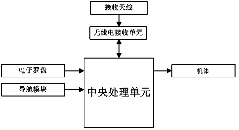
[0062] Aerial intelligent robots for radio monitoring, including:

[0063] airframes for flight;

[0064] Receiving antennas for acquiring radio signals;

[0065] An electronic compass used to obtain the direction pointed by the receiving antenna and obtain the azimuth corresponding to the direction in real time;

[0066] a radio monitoring receiving unit for receiving radio signals;

[0067] A central processing unit for dispatching monitoring tasks, controlling airframe flight, dispatching radio monitoring receiving units, analyzing monitoring data and recording monitoring data;

[0068] Navigation module for navigation and self-positioning;

[0069] The receiving antenna, the electronic compass, the radio monitoring receiving unit, the central processing unit and the navigation module are all installed on the body, and the central processing unit is connected with the navigation module, the electronic compass and the radio monitoring receiving unit respectively, and the ...

Embodiment 2

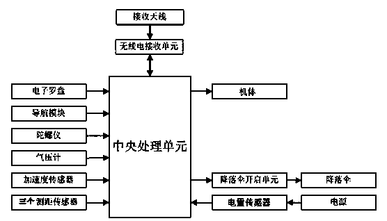
[0091] An aerial intelligent robot for radio monitoring, characterized by comprising:

[0092] airframes for flight;

[0093] Receiving antennas for acquiring radio signals;

[0094] An electronic compass used to obtain the direction pointed by the receiving antenna and obtain the azimuth corresponding to the direction in real time;

[0095] a radio monitoring receiving unit for receiving radio signals;

[0096] A central processing unit for dispatching monitoring tasks, controlling airframe flight, dispatching radio monitoring receiving units, analyzing and recording monitoring data;

[0097] Navigation module for navigation and self-positioning;

[0098] The receiving antenna, the electronic compass, the radio monitoring receiving unit, the central processing unit and the navigation module are all installed on the body, and the central processing unit is connected with the navigation module, the electronic compass and the radio monitoring receiving unit respectively, and ...

Embodiment 3

[0119] An aerial intelligent robot for radio monitoring, characterized by comprising:

[0120] airframes for flight;

[0121] Receiving antennas for acquiring radio signals;

[0122] An electronic compass used to obtain the direction pointed by the receiving antenna and obtain the azimuth corresponding to the direction in real time;

[0123] a radio monitoring receiving unit for receiving radio signals;

[0124] A central processing unit for controlling the flight of the airframe, scheduling direction-finding tasks, analyzing and recording monitoring data;

[0125] Navigation module for navigation and self-positioning;

[0126] The receiving antenna, the electronic compass, the radio monitoring receiving unit, the central processing unit and the navigation module are all installed on the body, and the central processing unit is connected with the navigation module, the electronic compass and the radio monitoring receiving unit respectively, and the receiving antenna is conn...


PUM


Abstract

The invention discloses an aerial intelligent robot used for radio monitoring. A receiving antenna, an electronic compass, a radio monitoring receiving unit, a central processing unit and a navigation module are all installed on a robot body; the central processing unit is connected with the navigation module, the electronic compass and the radio monitoring receiving unit; the receiving antenna is connected with the radio monitoring receiving unit; the central processing unit firstly conducts direction finding to find the direction of a radio signal source, then automatically controls flight of the robot body according to direction finding results, and finally calculates the position of the radio signal source according to data further monitored on flight tracks. According to the aerial intelligent robot, one central processing unit is used for controlling radio monitoring and flight of the robot body at the same time, the number of modules is decreased, and mutual interference is reduced; in addition, the integration degree is high, the size is greatly reduced, the power dissipation is reduced, and the electromagnetic compatibility is better.

Description

technical field [0001] The invention relates to the field of aerial radio monitoring, in particular to an aerial intelligent robot for radio monitoring which utilizes direction finding results to autonomously plan a track to locate a signal source. Background technique [0002] As a supplement to the traditional monitoring mode, aerial radio monitoring can form a multi-functional modern three-dimensional monitoring network such as remote control, joint direction finding, and key monitoring on the existing monitoring network, which will realize full-frequency, full-service, Full-time and all-round monitoring coverage, so as to comprehensively improve the level of technical management. The biggest difference between aerial monitoring and previous monitoring methods is the need for the use of carriers suitable for aerial monitoring flights, and different monitoring activities have different requirements for the types of monitoring carriers used in terms of the needs, nature and...

Claims


Application Information

Patent Timeline
Patent Type & Authority Applications(China)
IPC IPC(8): G01S3/14G01S5/02
CPCG01S5/0263
Inventor 崔铠韬马方立裴峥孔明明何永东白宇军邱承跃
Owner XIHUA UNIV
Why Eureka
Try Eureka