
Fiber jumper wire joint and large-power semiconductor laser assembly

An optical fiber jumper and optical fiber technology, which is applied in the field of communication, can solve the problems of burning out the optical fiber, difficult processing and short life, and achieves the effect of improving reliability and service life and being widely used.

Inactive Publication Date: 2015-01-28
WUHAN RUIZE TECH DEV +1
View PDF6 Cites 7 Cited by
  • Summary
  • Abstract
  • Description
  • Claims
  • Application Information

AI Technical Summary

Problems solved by technology

However, the traditional SMA connector fiber jumper is mainly used in the transmission of low-power optical signals in optical communication. After being applied to high-power semiconductor lasers, the traditional fiber jumper will have many problems.
The coaxiality of the ferrule, ferrule sleeve, nut and other components of the traditional optical fiber jumper must reach a very high precision to meet the replaceable requirements, and the processing is difficult, requiring ultra-high precision molding or machining processes production, higher cost
Secondly, the traditional optical fiber jumper is used in optical fiber communication, which transmits low-power light. Generally, glue is used to fix the optical fiber. The position of the optical fiber is in the center of the ferrule, and the end face of the optical fiber is exposed to the air. The end faces are even, and after being used in high-power semiconductor lasers, due to the poor heat dissipation of the glue, part of the light energy leaked from the fiber head cannot be dissipated, causing the fiber to be burned out. The reliability of high-power semiconductor lasers is low, and the lifespan short

Method used


Image

  • Fiber jumper wire joint and large-power semiconductor laser assembly
  • Fiber jumper wire joint and large-power semiconductor laser assembly

Examples


Embodiment Construction

[0019] The following will clearly and completely describe the technical solutions in the embodiments of the present invention with reference to the accompanying drawings in the embodiments of the present invention. Obviously, the described embodiments are only some, not all, embodiments of the present invention. Based on the embodiments of the present invention, all other embodiments obtained by persons of ordinary skill in the art without making creative efforts belong to the protection scope of the present invention.

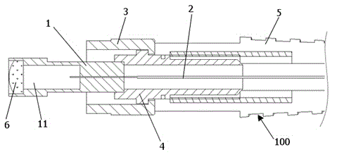
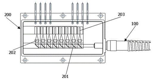
[0020] like figure 1 and figure 2 , the embodiment of the present invention provides an optical fiber jumper connector 100 , including a ferrule 1 , an optical fiber 2 , a ferrule holder 4 and a metal connector 3 . The front end of the ferrule base 4 is connected to the ferrule 1, the metal connector 3 is sleeved on the part where the ferrule base 4 is connected to the ferrule 1, and the optical fiber 2 passes through the ferrule base 4, and extend into the...


PUM


Abstract

The invention relates to a fiber jumper wire joint. The fiber jumper wire joint comprises an insertion core, a fiber, an insertion core seat and a metal connecting piece. The front end of the insertion core seat is connected with the insertion core, the metal connecting piece sleeves the connecting position of the insertion core seat and the insertion core, and the fiber passes through the insertion core seat and extends into the insertion core; the insertion core is internally provided with an accommodation space, a collimating lens is installed in front of the accommodation space, the collimating lens is disposed at the front end portion of the insertion core, the front end portion of the fiber is disposed in the accommodation space, and the accommodation space is a sealing space; and the front end portion of the fiber is disposed at the focus of the collimating lens. The invention also relates to a large-power semiconductor laser assembly cooperating with the fiber jumper wire joint for application. The fiber is sealed in the insertion core, the collimating lens exposed in environment has a quite large relative dimension, laser energy is quite dispersive, the reliability of the fiber jumper wire joint is improved, and the service life of the fiber jumper wire joint is prolonged. Compared to a conventional SMA fiber jumper wire joint, the fiber jumper wire joint and the large-power semiconductor laser assembly are more reliable and have wider application.

Description

technical field [0001] The invention relates to an optical fiber jumper joint and a high-power semiconductor laser assembly, which are used in high-power semiconductor lasers and belong to the communication field. Background technique [0002] Due to the advantages of small size, light weight and high efficiency, semiconductor lasers are widely used in many fields such as industry, military, medical treatment and communication. Due to the limitation of its own quantum well waveguide structure, the output beam quality of semiconductor lasers is poor compared with traditional lasers such as CO2 lasers and solid-state YAG lasers, which hinders the expansion of its application fields. In recent years, with the development of semiconductor material epitaxial growth technology, semiconductor laser waveguide structure optimization technology, cavity surface passivation technology, high stability packaging technology, and efficient heat dissipation technology, especially in direct s...

Claims


Application Information

Patent Timeline
IPC IPC(8): G02B6/38
CPCG02B6/3853
Inventor 卢昆忠周毅明王文娟
Owner WUHAN RUIZE TECH DEV
Learn More