Check patentability & draft patents in minutes with Patsnap Eureka AI!

Projection device

A projection device and area technology, applied in projection devices, optics, instruments, etc., can solve the problem of image position offset and other problems, to achieve the effect of controlling image offset and avoiding thermal expansion and cold contraction

Active Publication Date: 2015-01-28
QISDA OPTRONICS (SUZHOU) CO LTD +1
View PDF8 Cites 1 Cited by
  • Summary
  • Abstract
  • Description
  • Claims
  • Application Information

AI Technical Summary

Problems solved by technology

[0004] Therefore, one of the objects of the present invention is to provide a projection device to solve the problem in the prior art that the position of the imaging picture is shifted due to the change of the external temperature of the lens.

Method used


Image

  • Projection device
  • Projection device
  • Projection device

Examples


Embodiment Construction

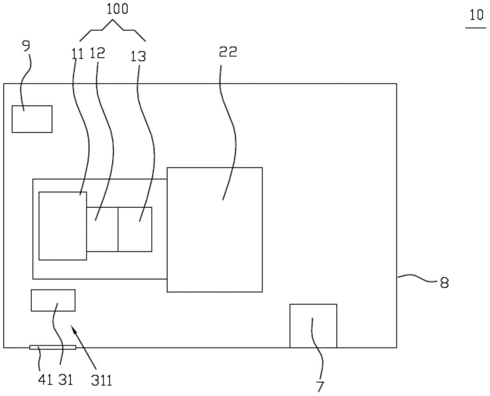
[0023] See figure 1 , figure 1 Shown is a schematic diagram of the first embodiment of the projection device according to the present invention; the present invention provides a projection device 10, the projection device 10 includes a housing 8, a lens 100, an optical engine 22, a first fan 31, and a sensing unit 9 As well as the control unit 7 , of course, the projection device 10 also includes other components, such as a light source module, etc., which are all prior knowledge, so they will not be repeated here. In addition, the present invention does not limit the installation positions of the optical engine 22 , the lens 100 , the sensing unit 9 and the control unit 7 in the housing 8 , and can be defined according to actual needs and actual conditions. The lens 100 is disposed in the housing 8 , and the lens 100 is fixedly connected to the optical engine 22 . The lens 100 has a first area 11, and the first area 11 is located at the first end of the lens 100 away from t...


PUM


Abstract

The invention discloses a projection device, which comprises a shell, a light machine, a lens, a first fan, a sensing unit, and a control unit, wherein the lens is arranged in the shell; the lens is provided with a first region; the first region is located at the first end, far away from the light machine, of the lens; the first fan is arranged adjacently to the first region of the lens for cooling the first region; the sensing unit is used for sensing the ambient temperature inside the shell; the control unit is used for adjusting the rotation speed of the first fan according to the ambient temperature; when the ambient temperature is larger than the preset value, the control unit improves the rotation speed of the first fan; and when the ambient temperature is smaller than the preset value, the control unit reduces the rotation speed of the first fan. Thus, the problem that the position of an imaging picture shifts due to temperature changes outside the lens in the prior art can be solved.

Description

technical field [0001] The present invention relates to a projection device, in particular to a projection device capable of preventing screen offset. Background technique [0002] Thermal expansion and contraction are the basic characteristics of physics. There are many reasons that affect the quality of the projector's imaging. For example, the optical-mechanical lens itself is made of glass, and even recently, the lens has been replaced by a plastic lens for cost considerations. The problem is that the plastic itself is highly variable to temperature changes. The temperature control inside the projector system is quite sensitive, such as the temperature of the bulb, the temperature of the optical lens clamping mechanism, the temperature of the optical imaging DMD, etc. There are also many other factors, such as the ambient temperature, cleanliness, The altitude of the location will affect the temperature in the system, which in turn will cause the screen projected by the...

Claims


Application Information

Patent Timeline
IPC IPC(8): G03B21/16
CPCG03B21/16
Inventor 丛志杰沈俊明李锦奎张书瑜杨家逢周秉忠
Owner QISDA OPTRONICS (SUZHOU) CO LTD
Features
  • R&D
  • Intellectual Property
  • Life Sciences
  • Materials
  • Tech Scout
  • Unparalleled Data Quality
  • Higher Quality Content
  • 60% Fewer Hallucinations
Learn More