Display panel driving method, driving circuit, and display device
A technology of a display panel and a driving method, which is applied to static indicators, instruments, etc., can solve the problems of horizontal stripes on the display panel, and achieve the effect of balancing brightness and eliminating X-Block.
- Summary
- Abstract
- Description
- Claims
- Application Information
AI Technical Summary
Problems solved by technology
Method used
Image

Examples
Embodiment 1
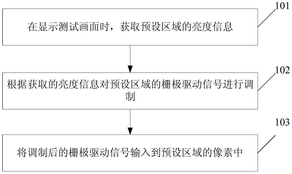
[0050] image 3 It is a schematic flow chart of the driving method of the display panel in this embodiment, as image 3 As shown, this embodiment includes:
[0051] Step 101: Obtain brightness information of a preset area when a test picture is displayed;
[0052] Wherein, the test picture is a solid color picture, specifically, the gray scale value of the test picture may be 127. The preset area can include one or more rows of pixels, and the picture information of the test picture can be collected by a data collection device such as a high-definition camera, and the collected picture information can be processed to obtain the brightness information of each area.
[0053] Step 102: Modulate the gate drive signal of the preset area according to the acquired brightness information;
[0054] Specifically, the data acquisition device can send the brightness information of the area to a data processor, such as TCON (timer / counter control register) or SOC (system-on-chip), and t...
Embodiment 2
[0059] This embodiment provides a driving circuit for a display panel, such as Figure 4 As shown, this embodiment includes:
[0060] A processing module, configured to obtain brightness information of a preset area when displaying a test picture;
[0061] a modulation module, configured to modulate the gate drive signal of the preset area according to the acquired brightness information;
[0062] The output module is used for inputting the modulated gate driving signal into the pixels in the preset area.
[0063] Further, the processing module includes:
[0064] A collection unit, configured to collect the picture information of the test picture through a data collection device;
[0065] The calculation unit is used to process the collected picture information to obtain the brightness information of the preset area.
[0066] Further, the modulation module includes:
[0067] The search unit is used to determine the waveform modulation signal corresponding to the gate driv...
Embodiment 3
[0079] An embodiment of the present invention also provides a display device, including the above-mentioned drive circuit for a display panel. Wherein, the structure and working principle of the driving circuit of the display panel are the same as those of the above-mentioned embodiments, and will not be repeated here. In addition, the structure of other parts of the display device can refer to the prior art, which will not be described in detail herein. The display device may be a product or component with any display function such as a liquid crystal panel, electronic paper, liquid crystal TV, liquid crystal display, digital photo frame, mobile phone, and tablet computer.
PUM
 Abstract
Description
Claims
Application Information
 - R&D
- Intellectual Property
- Life Sciences
- Materials
- Tech Scout
- Unparalleled Data Quality
- Higher Quality Content
- 60% Fewer Hallucinations
Browse by: Latest US Patents, China's latest patents, Technical Efficacy Thesaurus, Application Domain, Technology Topic, Popular Technical Reports.
© 2025 PatSnap. All rights reserved.Legal|Privacy policy|Modern Slavery Act Transparency Statement|Sitemap|About US| Contact US: help@patsnap.com