Location grid rack provided with streamline low pressure drop runner, and fuel assembly

A positioning grid, low pressure drop technology, applied in the direction of reactor fuel elements, nuclear power generation, climate sustainability, etc., can solve the problems of increased fluid pressure loss, unfavorable pressure maintenance, fuel rod scratches, etc., to avoid vibration, Effect of fluid pressure drop and pressure loss reduction

Active Publication Date: 2015-01-28
LINGAO NUCLEAR POWER +3
View PDF8 Cites 5 Cited by
  • Summary
  • Abstract
  • Description
  • Claims
  • Application Information

AI Technical Summary

Problems solved by technology

[0004] Although the process of stamping and forming the rigid convex a on the inner strip b is relatively simple, there are two defects in the structure of this semicircular rigid convex a: first, when the coolant flows through the spacer from bottom to top, it is located at the bottom The semicircular just convex a has a larger frontal area (a quarter of a sphere), which produces greater resistance to the fluid, which is not conducive to maintaining pressure, and the interior of the semicircular just convex a above will form a void. The coolant flows into the cavity to form a vortex, which increases the pressure loss of the fluid; second, when the fuel rods are loaded from top to bottom, the upper end of the semicircular just convex a located below in the grid unit has a section, There is a possibility of scratching the fuel rod, causing scratches and damage to the surface of the fuel rod

Method used


Image

  • Location grid rack provided with streamline low pressure drop runner, and fuel assembly
  • Location grid rack provided with streamline low pressure drop runner, and fuel assembly
  • Location grid rack provided with streamline low pressure drop runner, and fuel assembly

Examples


Embodiment Construction

[0027] The preferred embodiments of the present invention will be described below in conjunction with the accompanying drawings.

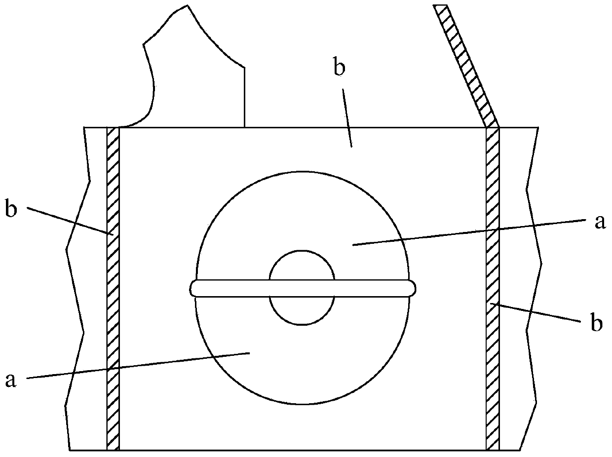
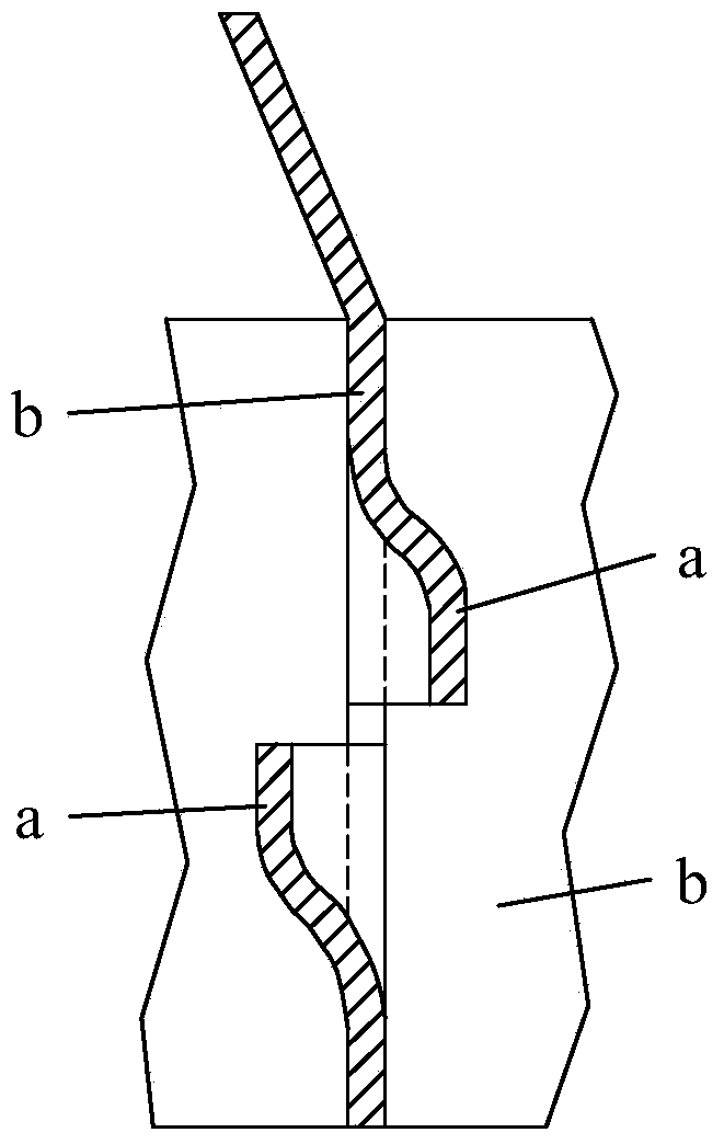
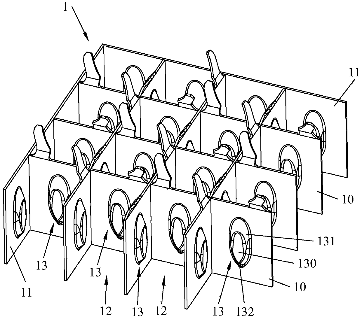
[0028] Such as Figures 3 to 5 Shown is a first embodiment of the invention. In this embodiment, a spacer grid 1 with a streamlined low-pressure drop channel is provided, the spacer grid 1 includes a plurality of inner strips 10 and outer strips 11, and a plurality of inner strips 10 intersect each other to form a The grid structure forms a plurality of hollow grid units 12 , the outer strips 11 surround the grid structure and are fixed to the inner strips 10 . The inner strip 10 is fixed with a rigid protrusion 13 protruding inwardly of the grid unit 12, and the rigid protrusion 13 includes a plane 130 in contact with the fuel rod 4 and is closed and smoothly connected to the plane 130 and the plane 130. On the side surfaces 131 between the inner strips 10 , the lowermost ends of the side surfaces 131 form downward corners 132 , and the grid uni...


PUM


Abstract

The invention discloses a location grid rack provided with a streamline low pressure drop runner. The location grid rack comprises a plurality of inner strip bands, and an outer strip band, wherein the plurality of inner strip bands intersect with one another, so that a latticed grid structure and a plurality of hollow grid units are formed; the outer strip band is arranged at the periphery of the grid structure in a surrounding way and is fixed together with the inner strip bands; rigid bulges are respectively fixedly arranged on the inner strip bands and extend towards the interiors of the grid units in a convex way; each rigid bulge comprises a plane and a side surface, wherein each plane is contacted with a fuel rod, and each side surface is smoothly connected between the plane and the corresponding inner strip band in a sealing way; a downward corner angle is formed at the lowermost end of each side surface; the at least one pair of rigid bulges which are arranged in an opposite way are arranged in each grid unit. According to the location grid rack, due to the ship-shaped structures of the rigid bulges, an incident flow area and fluid eddies are reduced, the pressure drop is reduced, and the fuel rod is prevented from being scratched. Correspondingly, the invention also discloses a fuel assembly provided with the location grid rack.

Description

technical field [0001] The invention relates to the technical field of nuclear fuel assemblies, in particular to a spacer grid with streamlined low pressure drop channels and a fuel assembly with the spacer grid. Background technique [0002] A certain number of fuel rods are arranged at certain intervals (such as: 15×15 or 16×16, etc.) and fixed into a bundle, which is called a reactor fuel assembly. The reactor fuel assembly is mainly composed of an upper tube seat, a lower tube seat, and a positioning grid ( Also known as mixing grid or holding grid), control rod guide tube and fuel rods. Among them, the positioning grid is used for loading and positioning fuel rods and is composed of a plurality of inner strips and outer strips, and the plurality of inner strips are orthogonal to each other to form a grid-like grid structure with a plurality of grid units, while the outer The straps are fixedly surrounded by the inner straps. Except for a few grid units used to set the...

Claims


Application Information

Patent Timeline
Patent Type & Authority Applications(China)
IPC IPC(8): G21C3/352G21C15/243
CPCG21C3/352Y02E30/30
Inventor 禹文池钱昕陈晓明周跃民李伟才卢志威张玉相颜景文
Owner LINGAO NUCLEAR POWER
Why Eureka
Try Eureka